Introduction
Lets start with saying that there are two types of turboprop engines. A fixed shaft engine works essentially the same as a piston engine with constant speed propeller. Manifold pressure is replaced by a torque gauge, there is a reduction gearbox between the engine and propeller system, otherwise its essentially the same, there also is only one RPM gauge. If you understand the constant speed propeller principle in connection with piston engines, this kind if turboprop engine should be clear also.
Free turbine turboprops are a bit more difficult to understand. They consist of a compressor section with a turbine to drive that compressor and an independently driven power section. The turbine of the power section is not mechanically connected to the compressor section, like this: propeller —| |— compressor. Therefore the engine itself and the propeller (still driven via a reduction gearbox) can each run at a different speed, the propeller won’t drag down the engine.
Related topics:
- Constant Speed Propellers:
- Basic propeller aerodynamics.
Engine Start
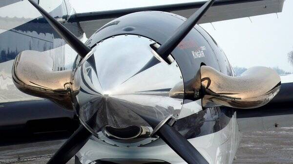
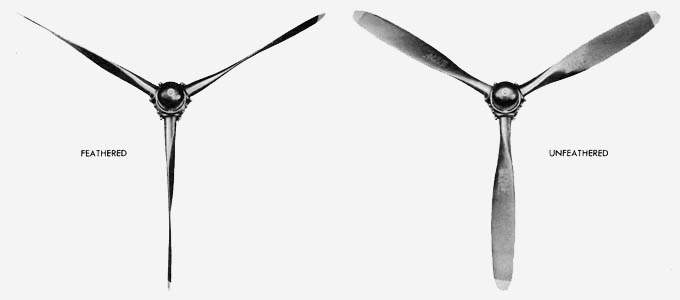
A free-turbine engine can start up with the propeller feathered , on a piston or fixed shaft turboprop you need start locks to hold the propeller in fine pitch during shutdown, otherwise you can’t start the engine back up as a feathered propeller would create too much load on the starter motor initially and later on the engine itself. The ATR for example can run the engine with propeller completely stopped (called “hotel-mode”), a propeller brake prevents the propeller from spinning while the engine itself runs normally. So from the outside you can immediately see if an engine is fixed shaft or free turbine by looking at the propeller position when the engine is shutdown.
Power changes
So to break down what happens on a free turbine engine when you apply power to the engine step-by-step:
- Fuel flow increases
- Energy in the exhaust gasses increases
- Energy extracted by the compressor section turbine increases, compressor section RPM increases.
- Higher mass flow through the engine.
- Energy extracted by the power section increases, propeller RPM tends to increase.
- The constant speed unit increases propeller pitch to maintain propeller speed constant.
- More thrust is produced due to higher blade angle on the propeller.
A free turbine engine response to power changes therefore isn’t as direct as on a fixed shaft engine. There is a bit of lag, especially at low power settings.
So on a free turbine engine the engine RPM is a separate thing from the propeller RPM, that is why you have two (or more) RPM gauges. You best notice this during engine start. You will hear the engine spooling up while the propeller slowly speeds up to operating speed. The engine (gas generator - Ng) speed is not something you use when setting power. It is however an important instrument during engine start and engine failure condition.
Power is set using torque, limited by ITT when hot and high. To make it more complex, some bigger engines have the two separate compressor sections and a power section. For example, the PW100 used on the ATR and Dash-8 has a NL (low), NH (high) and NP (propeller) speed indicator. NH is used during engine start and failure, NL is never used in normal operation. They all run independently of each other, RPM drops off differently across the different spools when applying or reducing power, making them all run at their most optimum operating speed.
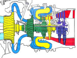
Free-turbine engine
You can see diagram of the PW100 engine used on the ATR and Dash 8 below. Those three different colored spools can all turn freely from each other. They are not mechanically connected. Basically their shafts run through each other freely.
- Green = NH
- Yellow = NL
- Blue = NP (only turbine visible)
On the PT-6 the free turbine principle is more clear as the engine and power section are physically separated from each other.
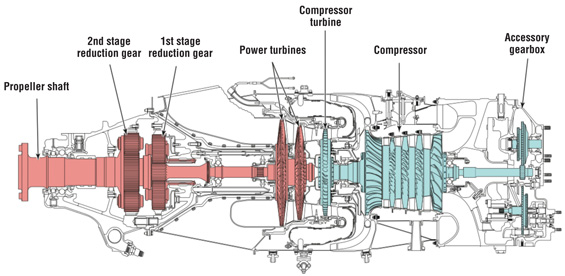
While the PW100 is direct flow, meaning the air enters the engine from the front and is expelled from the rear (fun fact, about 10% of the thrust produced by a turboprop is coming from energy still present in the exhaust gasses, producing a bit of residual jet thrust like a “normal” jet engine). The PT-6 is reverse flow, meaning that the engine is flipped around, the air enters the inlet, is turned around 180 degrees to enter the compressor, then goes through the engine from rear to front, turned around 180 degrees after the turbine section and expelled overboard. The exhaust pipe on the Kingair or TBM might give you a clue.