Reports are saying that the banking with the AP is “Not Right” and this may well be so.
So lets look at the Bank & Heading when entering a turn and leaving a turn to see quantitatively what it is really doing, and then we should be able to have a reference if we go crazy, changing flight_model.cfg parameters !!
Thanks to the marvels of Simconnect, we can get plot of how these two variable interact, which is far more repeatable and easier to analyses, that Video of the plane flying, or Pilot “perception”.
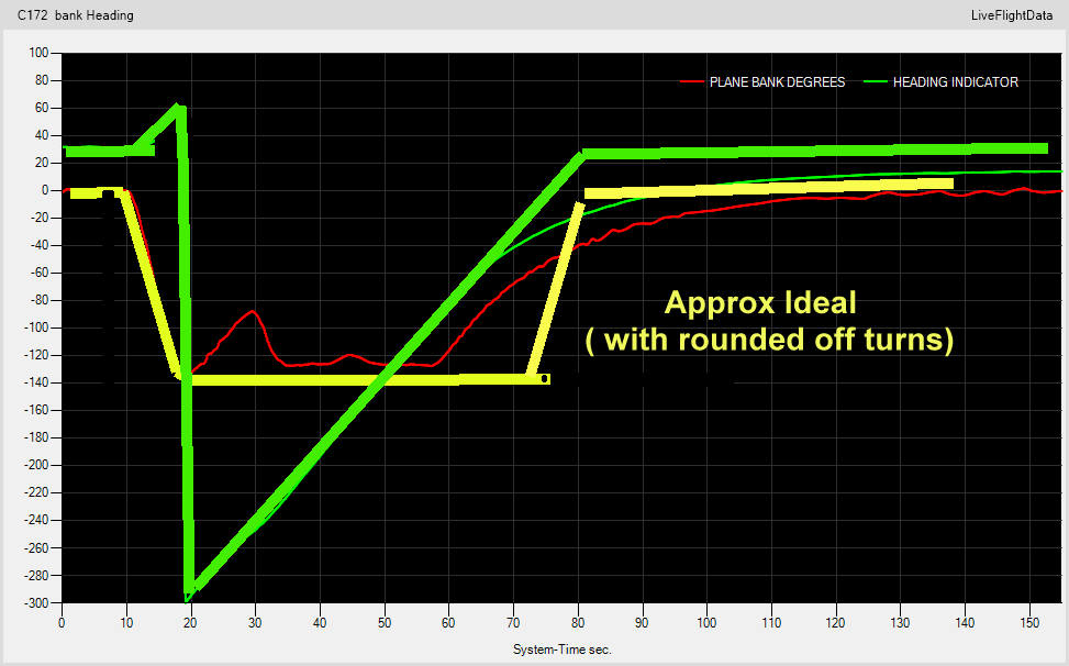
So here it is, Entering and leaving a 360 degree turn, with the heading demand about 160 degrees in advance of the heading, (This will prove to be more important than it should be , as well look at this behavior - but 1st, the MEAT !!!
1st thing you notice, that jumps out at you and smacks you in the face …
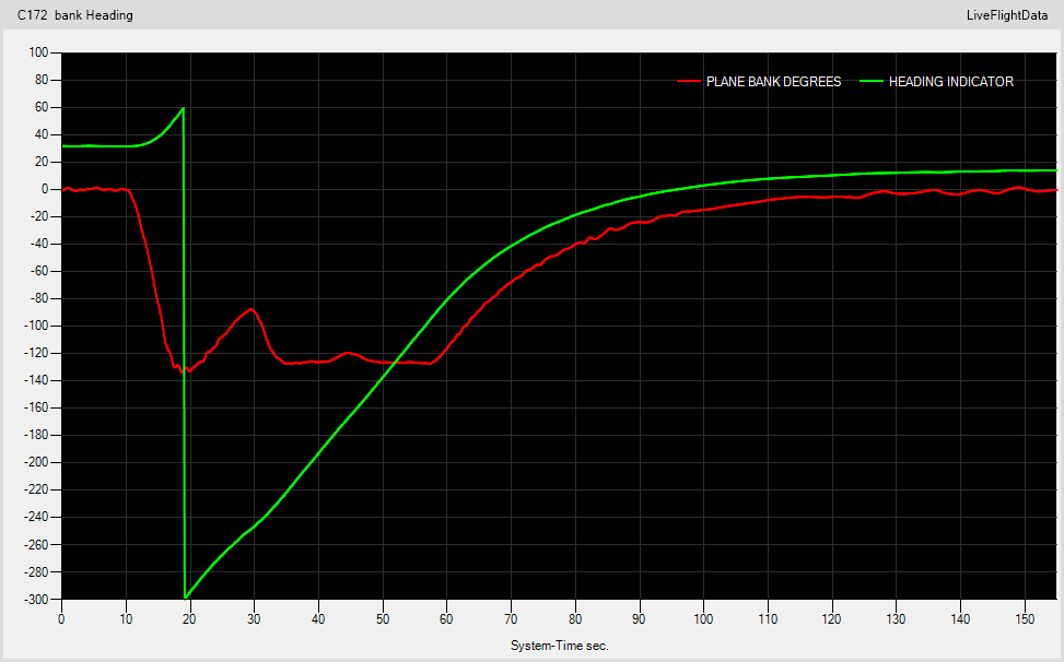
The difference in ENTERING the Turn ( at the start 10-20 = 10 seconds) and the sluggish way it EXITS the turn.(60 - 110 = 50 seconds)
So, what needs to be changed ?
Does anythiing need to be changed ?
What is the Real World response we would aim to achieve ?
A very good idea to analyze the behavior this way!
However the plot depicted here is a bit weird. The y axis seems not correct for the bank angle (max bank angle would be 130°). And in the heading curve, there is a jump of sign from +60 to -300. Of course there is no actual jump in heading. With the jump removed, we would see a smooth curve from 0 to 360 (plus some initial angle), still sluggish of course, but less confusing.
What we see in the plot is in the end the step response of the autopilot’s PID controller (or whatever type of controller is implemented). The tuning of the controller’s parameters determine the response time. If it is tuned poorly, response is slow (what we see me). If it is tuned to agresively, overshoots and oscillations can occur (what we saw pre-patch - at least from what I read in the forum, did not test it myself). The Wikipedia article depicts quite nicely the dependency of the step response on the tuning parameters:
OOps, I forget to indicate that the bank angle is X5 on the scale. and the headimg was heading -300 (from some other plots I was last doing - should have checked that )
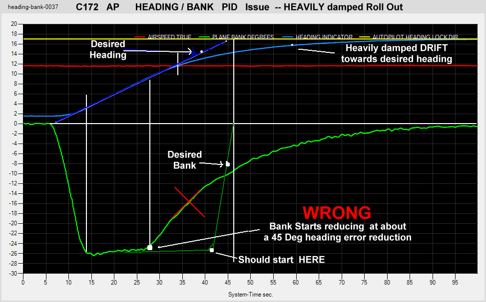
Its not so much the absolute Bank angle that is important here, its how it only decreases at the plane reaches its desired heading. Setting max bank angle is easy, its the Gain, I & D that is out here to get a more responsive system that does not overshoot …
or, really, what is REALISTIC.
The jump is as the heading flips going through North.
Its the response of returning to level after the bank that is painfully “underdamped”
I’ll designed more PID controlled systems than I care to think about
The heading should be a straight line, at a slope, with its ends rounded of to the horizontal.
The bank should Increase to max bank, stay there (Flat), and then only return back to zero, at the same rate it entered the bank, .
Then the response should be optimized, for “REQUIRED” rate of change, with minimum overshoot. at reaching BANKED, and at reaching LEVEL.
It seems you know more about PIDs than I do so please correct me if I’m wrong but I would disagree that it should enter and exit the bank necessarily with the same rate. The initial response to a setpoint change can be very fast. But I suppose not only the max bank angle but also the max bank angle change rate should be limited to some reasonable value, so If the controller is fast enough it would hit this limit most of the time and your yellow curve would be realized.
By the way, I do not know how such a limiting affects the overall performance of a PID. Do you?
I have the feeling that they just increased the I-part massively to get rid of oscillations and this results in a strongly overdamped system.
I don’t know how real autopilot systems are designed concerning the question if a slight overshoot is acceptable or if the systems has to be overdamped. But certainly not as overdamped as it is in the sim now.
Could you record some more step responses for different set-point changes? Would be interesting if it depends on that.
The variations of the bank angle that we see during the “constant” phase might be due to wind effects? Or was that you changing the heading setpoint further?
Enter & Exit rates should be whatever they are in Real World, Its up to the sim to simulate that.
Yes, they may not necessarily be the same, and yes, rate of change of bank angle (velocity) and its 1st derivative (rate of change of rate of change - Acceleration) are also of importance, and should be controllable … "It’s only software- you can make it do almost anything you want – the secret is, making it do what you need)
|
Not sure exactly what you mean, but yes, as well as P I D, you can set limits for Position, velocity and acceleration within a PID system.
|
I will be able to answer that with some confidence, when I have looked at past version backups. Considering a simole Spreadsheet to keep track of past & future changes. Compaing individual .cfg file fast becomes a tiresome task.
|
I have never designed a Plane’s Autopilot, but the ideal “might” be critically damped, with acceptable acceleration and deceleration, for both the plane and the pilots well being. !!
In any case, its not so much as a need to “DESIGN” a plane’s AP, but more to Simulate existing Real World systems … the design part has already been done.
|
Sure I can, but maybe once I have a set of parameters for large heading changes.
Then the small heading change responses should be acceptable, and be what they are.
|
No wind, it was due to not keeping the demand 170deg ahead of the current heading – something I eluded to as being a concerns, after the main “MEAT” course.
In any case, its not so much as a need to “DESIGN” a plane’s AP, but more to Simulate existing Real World systems … the design part has already been done.
Yeah I mean they have to implement a controller that acts on the simulated actuating variables (which are the ailerons etc). Of course you could hack in some behavior directly but that is not how it should be - and I guess also not what your are proposing. With “design” I meant implementing/tuning the controller so that it acts reasonably and realistically.
Be that as it may, in the end this should be no rocket science to realize this (also rocket science is no rocket science in my opinion ).
I played a bit with the SimConnect package for python and read out and plotted some variables. I saw that the bank max is 25° ( at least in the DA62). It goes into the bank with a constant velocity then stays at the 25° but then the overdamped behavior kicks in. Of course if the heading demand is not far away from the actual heading, you find yourself in the overdamped region immediately.
In turning flight, the number of degrees of heading change per unit of time (usually measured in seconds) is referred to as the rate of turn. By definition, a rate one or standard rate turn is accomplished at 3°/second resulting in a course reversal in one minute or a 360° turn in two minutes. A rate one half turn is flown at 1.5°/second and a rate two turn at 6°/second.
The bank angle required to conduct a turn at a specific rate is directly proportional to True Airspeed (TAS). The approximate bank angle required to accomplish a coordinated rate one turn (3°/second) can be calculated by dividing the TAS (in knots) by 10 and then adding 7. Using this formula, an aircraft flying at 80 knots would require 15° of bank for a rate one turn whereas at 160 knots, 23° would be required and at 240 knots a bank angle of 31° would be required to achieve the same rate of turn. As high bank angles are undesirable, especially in Instrument Meteorological Conditions (IMC), International Civil Aviation Organisation (ICAO) guidance for holding procedures states that “all turns in nil wind should be at a bank angle of 25 degrees or Rate One, whichever requires the lesser bank”. Protected airspace is then based on the radius of turn for the maximum allowable holding speed at 25° of bank.
ie Bank Angle = ( TAS / 10 ) + 7 degrees
So any plots of Heading & Bank Angle vs Time should also include plot of TAS. not that the KAP130 AP knows your TAS, to be able to set the appropriate bank angle , to always turn with a Standard Rate turn.
The above Plots clearly show what is wrong. (12/3/2020)
Until the GA Heading/Bank PIDS are corrected, any NAV Pids trying to intercept and track a course will never be correct.
At the moment the whole systems is so heavily (Unrealistically) Damped, (I assume to try to stop oscillation) that the overall AP performance is Terrible.
The current seemingly RANDOM changing of PID parameters, either exposed to the user (.cfg files) or in hidden “code” stands very little chance of hitting an anywhere optimum solution.
The PIDs have to be set up and adjusted in a logical procedure, to make each be tuned correctly, especially when when they are cascaded.
Putting it into Business terms, DOLLARS – It far cheaper to do it right the first time, than to keep throwing time & money at it, trying to weak it in an uninformed manner.
Well, seems there is very little interest in this subject (apart from by marccreal – thank you for the input)
Personally, I see no point in further trying to bringing this subject up again.
One day it may get fixed, maybe it will never get addressed.
I shall watch with interest, because probably, if it does get fixed, and fixed correctly, that may well be a sign that Asobo is getting some Aviation Technical Knowledge, somehow.
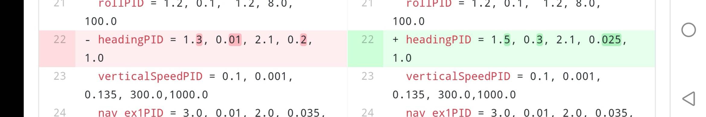
Mainly the values corresponding to I have been changed (which fits to our analysis). Seems that Ik and I boundary have been swapped (and slightly modified).
Would be interesting to modify the values of the C172 accordingly and measure the curves again.
Edit: here the corresponding change in the A32x mod:
 )
)