I’m more than willing to share my files free of charge. I like the interactions on the forum, the discussions about the solutions, getting feedback and advice, etc… No money that can replace that ![]()
Sorry, forgot to answer your first question. When I did some research on A320 encoders some years ago, I think I found some info where it said that a full turn is 24 ticks. Not sure if that is true or not, but for me it works very good. If I’m not mistaken, I also used the FBW A32NX simulator, made a full turn, and looked how many steps that was. As you know, “research” is half of the fun ![]()
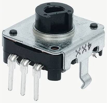
As mentioned earlier, I use an encoder without shaft. I used to buy a few from RS-Online, but there it is now obsolete. I luckily found them also on AlieExpress (see here), where I immediately purchased about 20 of them. If you want to google them, the type is EC12E2420301. On RS-Online you even can download a detailed model for Fusion 360.
I made my own rod - below the design in Fusion 360. I’m using a plastic tube of about 6mm diameter (I think I purchased about 5 x 1 meter of that on AlieExpress for about 10 € - good for more than 10 years!).
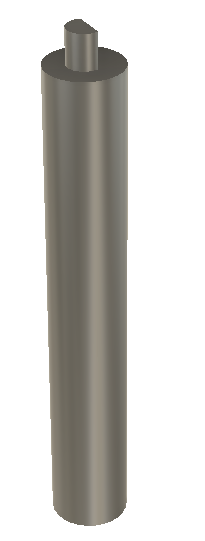
The D-shape on top is done with my desktop CNC machine. The biggest challenge there is positioning the rod to do the cut - trial and error, and patience… again.
The rod is glued with superglue on the encoder. I even made a positioning tool with my 3D-printer (same machine - as you know, Snapmaker can do 3D, CNC and laser) to make sure that the rod is perfectly vertical. The last thing you want is that the rod is not perfectly on axis (yep, all part of the “trial and error” process - been there, done that - and then thinking of “how can I improve it”).
Hello ,
First of all, very well done on the build. yours is one the cleanest ive seen. I am too in the process on making my own MCDU, ive finish with the PCB , faceplate and programming using Mobiflight. The only thing I need to do is the keycaps for the MCDU and the housing.
Can I ask though, what method did you use for the keycaps? I am thinking resin printer then etch with laser for the letters but some recommended acrylic. How did you create yours? Thanks
Hello,
These are all made out of acrylic. I don’t have a resin printer, and honestly, I have better precision with my CNC.
I really went for the details here. As you can see, the upper side even has a kind of sphere like cutout, just like in the real thing.
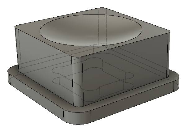
At the bottom, I have some cutout that fits perfectly on my push buttons.
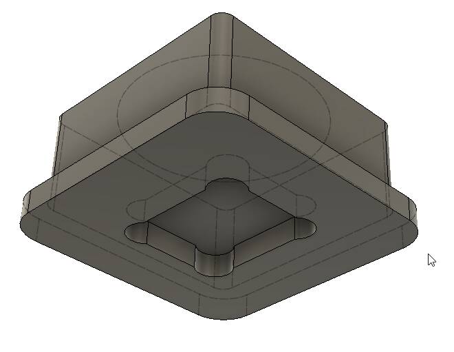
At the bottom, I also have some kind of rim that has 2 functions. One is to avoid the button of falling out of the panel (which even means that I don’t have to use glue, which also improves serviceability). Second is to act as a light blocker, because I hate it that too much light escapes at the sides (I’m a perfectionist ![]() ).
).
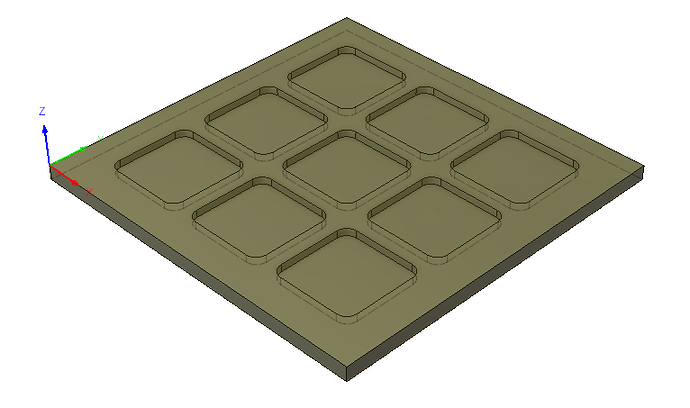
I then spray-painted them in black, and after that I used my laser for the print. To make sure that the print is at exactly the correct position (slightest deviation can be visible on such small parts), I created some “holders” that allowed me to hold the buttons at exact locations. I can then laser 9 of them in one go. I use Inkscape to make my designs.
Aligning is the crucial part. I developped some workflow with my Snapmaker CNC/laser in which I use a “square” (not sure if that is the right word in Engish) that I position very precisely using a 1.5mm. I connect the square with one lead and the bit with the other lead of a “ohms-meter”. Then I move my head 0.1mm at a time until I hear a beep. This allows me to very precisely position the square. Then I position the laser as good as possible in the corner of the square, and then do a first callibration run with a piece that I first laser and then turn 180° and laser again. Then I can measure the difference that I can use to adjust the head in X and Y. Now I’m sure that the corner of the square is exactly at 0,0. I can then put my key cap holder in that corner, and all lasering is perfectly done. I use this same principle to print the upper and bottom part of acrylic components.
I designed my buttons and the holders in Fusion 360 (free version), which easily allowed me to create all the toolpaths for my CNC. If you’re interested, I can provide you with the f3d-files.
Hi HBilliet, wow your work is amazing. I have decided to build my own A320 cockpit, but step by step. First the FCU and then the MCDU. My question is, can I have more information from your work? For example dimensions, files ect. Simply intended for the replica. If not via this forum, then via email or other. Or do you not want that? Of course it’s easy for me if I just ask you. But why not learn something from someone. I have to assemble it myself anyway.
Thanks
Marco
Hello Marco,
Thanks for these nice words. Not sure what platform you are going to use to communicate with your hardware, but I just released CockpitHardwareHUB_v2 on GitHub. It includes all executables and WASM module.
I’m thinking of making a website, in which I will share a lot of my stuff. The problem is, there is a LOT! Not something that you share in just one email. If you work with Fusion360, I could send you some files.
Hans
Thank you very much, Hans
best regards
Marco
Pretty…
How do You like the Luban software. I’ve never been a fan and have tried it with each big update. It is definitely not Snapmaker’s strong suit.
Like you, I use F360 for the CNC work (but also for all the model work) and Cura for slicing. But I use Lightburn for the laser work. It’s a great program for $30 a year.
Have you considered using F360 for the PCB? I may give it a go for my C-182RG radio Stack that I’m working on. Did you receive your PCB bare and do your own soldering or did you order it as a completed unit?
Hello,
I’m not a big fan of Luban. I prefer Cura. Although, I do use Luban to import my laser-designs from Inkscape to convert in the files that I can load in my Snapmaker.
I’m using F360 also for my designs. I used to work with SketchUp, because F360 has a lot steeper learning curve. But suddenly I started to take my time for it, and now I don’t want to use anything else. It’s a great tool, and much better in a lot of aspects as SketchUp (SketchUp gets messy sometimes if you try making complex designs).
So to summarize, these are my workflows:
- For 3D: Design in F360 → *.STL Export as 3D → Import in Cura → *.GCODE Export for Snapmaker
- For CNC: Design in F360 → Toolpaths in F360 → *.CNC Export for Snapmaker
- For Laser: Design in F360 (sketch with all items that needs to be lasered) → Save sketch as *.DXF → Import in Inkscape → Export as JPG → import in Luban → *.NC Export for Snapmaker
I haven’t used PCB design in F360. This would be another steep learning curve. In my designs in F360, I also have a sketch with the PCB and all its cutouts, and I export this as DXF. Then I can import this in EasyEDA on the BoardOutLine layer.
Best regards,
Hans
Your parts look pretty amazong! What display do you use for the MCDU? I’m already searching a while for a suitable display module, but haven’t found one so far
Hello @HoneyScammer,
I used the 5.6 inch AT056TN53 V.1 640x480 LCD screen, including the HDMI VGA Controler Driver Board.
I purchased it via AliExpress. You find it here.
I took this one, because it perfectly fits the dimensions of the MCDU. And 640x480 is all you need, because it’s only text it needs to display.
Greetz
Hello, very well done job here.
I have a question about the 7 segment displays on the FCU, I want to build my own, but im pretty stuck on the 7 segment displays and the indicators above them. Can you share, how did you make the panel look so realistic? Thanks for answer.
Hello @WedCylinder1769,
I’m using a combination of 7-segment displays and orange LED’s.
- For the 7-segment displays, I use OPD-S3011LA-BW. This is the Common Cathode version (works perfect with MAX7219CWG). But also the “BW” version, which has a black front, which blends better with the rest of the black front.
- For the orange LED’s, I used the TH Panasonic LNJ876YK6AA. Unfortunately, I don’t think you can find them any longer. For my EFIS (work in progress), I’m using an alternative SMD HL-PSC-2012S22OC from Honglitronic. Most important is that the color has about the same wavelength as the 7-Segment display, which is around 600 nm.
- For the front plate, I’m using transparent plexiglass. I painted the back in black (don’t use a primer, because that reduces the blackness), and then used a laser to remove the characters. Except for the cutouts of the 7-Segment displays, I used some tape to avoid that these areas are coated with paint. Removing such large areas with the laser always leaves some “scratches”.
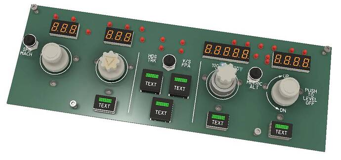
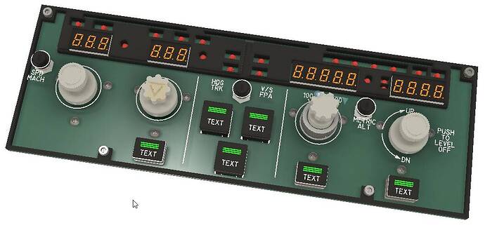
- To make sure that the light of the LED’s is guided, I used my 3D-printer to create a kind of spacer that encapsulates the LED’s, as you can see in below picture. This spacer is also used as a border around the PCB, to keep the front panel at the correct distance.
The above is based on a few trial and errors, with the best result as described above.
Small detail - the +/- before the V/S is also based on 2 LED’s, because I didn’t find a solution with 7-Segment displays. I know that +/- exists, but trying to find them in the same size, black front, and color seemed an impossible task.
I hope that this info is helpful. If you have more questions, don’t hesitate to ask.
Hans
Hello, thanks a lot for a answer,
Thats a smart idea with the front plate, Ill try it, so just pain the plexiglass black and laser engrave the text (such as SPD, MACH and so on).
Also how did you make the whole gray front panel? I was thinking about 3D printing, but i dont know how to handle the text and backlight? Is it same method with painting and laser engraving?
Thanks again for your time!
Hello @WedCylinder1769,
Yes, you are right. It’s as “simple” as that! Don’t forget to mirror your laser pattern, because it needs to be put at the back of your transparent plexiglass.
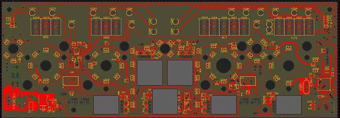
For the front plate, I’m using the same method. I used a white opaque plexiglass, paint it gray (RAL 7031), and then I’m again lasering the text/graphics. On my PCB, I’m using white LED’s to serve as backlighting. Because the plexiglass is opaque, the light is nicely spread. My panel is at about 5mm from my PCB, on which I put SMD LED’s at maximum distances of about 10mm from eachother to have a good equal light spread. As you can see in below PCB layout, there are a lot of LED’s (I have 59 backlighting LED’s).
To make my life easier, I’m using the SMT service of JLCPCB to put the LED’s already on the PCB, so I don’t have to do all that soldering myself.
The only disadvantage of this method is that in daylight without backlighting, the characters/graphics are very faint. I can live with that, because I intend to use my panels always with backlighting.
I once found a video on YouTube of somebody that created front panels with 2 colors (gray and white). He used a 0.2mm nozzle for high precision. He used a Bambu lab 3D printer if I remember well, which can handle multiple colors. I was really surprised with the result - although unexpected the characters looked perfect. And there, the advantage is that the white looked really white in daylight. I lost the video, but if I could get in touch with that person, I would like to ask him to do a test and print my panel (I would provide design and pay him of course). If the results would be as expected, I might buy a Bambu lab 3D printer as well, because doing it this way has a lot shorter workflow.
EDIT: I found the video back. https://youtu.be/WIdHBMIfGhQ?si=Yd6ikdlKWV-S_G1x
I have 3D printed an A320 EFIS in grey with white lettering on my Ender 3V2.
I programmed a filament change at layer 19, when the panel was 3mm high. Then switched to white to print the text which is 1mm high
It looks clear using a 0.4mm nozzle, I experimented with a slightly larger Arial font to maximise the letter size
Why not just use 2 color plastic sheets from Rowmark and laser them. The letters are bright white and very precise, and you can shine any color LED through them for backlighting. I thought I had shared this with you previously but I guess I didn’t. Oops…
You do need to spray it with a clear protectant acrylic to prevent scratching after you’re done lasering them. I use photo protectant spray paint from Michaels.
I mount the sheet to the CNC bed. Then laser with the laser head. Then swap out for the CNC head and cut it out without removing it from the CNC bed. Once I figured out the process, I began using it for all my faceplates and button tops. If you use illuminated tactile switches, they will shine through the button tops.
Here’s a pic of my button box. All the buttons are 3D printed and capped with lasered inserts.
https://forums.flightsimulator.com/uploads/default/original/3X/7/4/749c8ce62a493caab0895f23d3381320dc8e6bd4.jpeg
Hello @jcslove,
That looks interesting. Just would need to find a RAL7035 for the front, because that’s the color of the panels in a A320.
So the principle is that the sheet has 2 colors (in your case white with a black top), and you remove the text/graphics with your laser from the black layer? This is the same principle as what I’m doing with my painted acrylic panels, but due to the fact that this is really white, it will indeed look a lot better in daylight.
Hello @TaurineCorn668,
I’m really surprised to read that you just use a 0.4mm nozzle. I’m afraid that for my character size, this won’t work (I want my panels to look as real, so I don’t want to use tricks like making characters larger). Do you have some photographs?
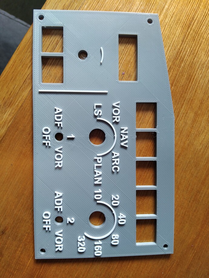
Here is a quick photo from my phone. The lens distorts the image of course.
The text is not perfect but I wear reading glasses so slightly larger and clearer is good for me. I’m not interested in a precise scale model, I just want a realistic cockpit that doesn’t need a mouse!
There seems to be an ideal font for a 0.4mm nozzle, on another panel I’ll try 0.2mm.
From a typical distance the text is ok, I will tidy the retract blobs with a scalpel in final assembly.
