Chapter 4: Connecting with Arduino
On GitHub, you will find an example Arduino sketch. This sketch is based on the below connection diagram which is meant for a MEGA 2560 R3:
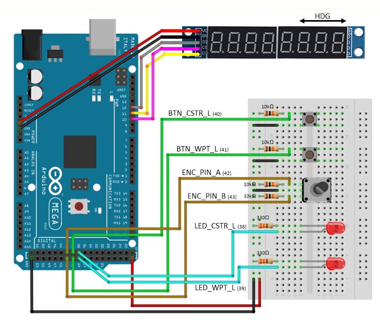
The example is meant for the FlyByWire A32NX. As the labels on the drawing already indicate, the demo controls the following:
- EFIS_L CSTR (button to control + LED to show if active)
- EFIS_L WPT (button to control + LED to show if active)
- 3 digits of 7-Segment display (based on MAX7219) to show the HDG
- Rotary Encoder to INC/DEC the HDG
Below I will explain step by step how to run the example, and what is happening behind the scenes.
1. Start the sim
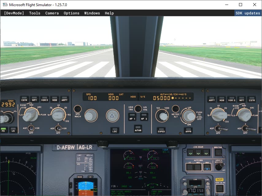
Launch MSFS2020. Make sure that “Developer mode” is enabled (From main menu, select Options/General Options/Developers and set Developer Mode ON). Select a flight with the FlyByWire A32NX (this is a free add-on that needs to be installed separately) and select the start of a runway as Departure. Once the plane is started with the engines running, press “CTRL-2” to show the Glareshield/FCU. You should get a view like below.
Use menu “Window/Console” to show the console window that will give some more info about the WASM module. Best is to filter “habi_wasm”, which will only show the messages generated by my own WASM module. If you have copied the WASM folder from GitHub in the MSFS Community folder, then the WASM module should start automatically, which will be shown in the Console window.

Remark: Version in screenshot could differ from the pre-built one on GitHub. If you rebuild the source code of the complete VS2022 solution, you should have the latest version.
2. Connect with Arduino
First power the Arduino and connect it with USB. When powering up, the 7-segment displays will probably flash on for a fraction of a second, and then dim completely.
Launch the Cockpit Hardware HUB and enable the logging. Then press the Connect button. A lot of things are happening at once now.
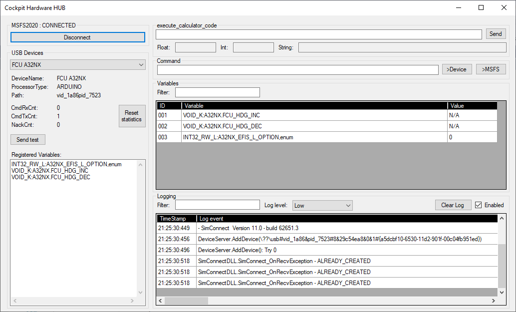
- The tool will first connect with MSFS2020 and start some processes to interact with SimConnect and WASM
- Next the USB modules that are already connected will be detected, and the tool will attempt to communicate with them. It’s very common that Try 0 will fail with a TimeoutException, but Try 1 should be successful. The tool will do a maximum of 20 trials, which in case of multiple USB devices will all run asynchronously.
- If a connection is established, the first command sent to the device is “IDENT”. The device will respond with a “DeviceName” and a “ProcessorType”. This is only informative, and is displayed in the “USB Device” field of the UI. In the screenshot this is “FCU A32NX” and “ARDUINO”.
- The second command that is sent to the device is “REGISTER”. That tells the device to send all the “Variables” it requires to the tool, terminated by an empty string.
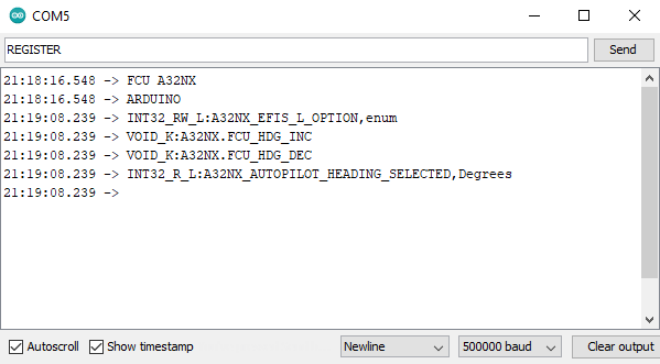
In the Arduino sketch, I store the variables in a const char* array, which makes it easy to keep track of the number to be used later on - see below.
// variables (variables start at 001
const char *Variables[] = {
  "INT32_RW_L:A32NX_EFIS_L_OPTION,enum",                // 001
  "VOID_K:A32NX.FCU_HDG_INC",                           // 002
  "VOID_K:A32NX.FCU_HDG_DEC",                           // 003
  };
- Once the variables are received by the tool, it will register them one by one. This is exactly the same as if you would do it manually by entering them one by one in the Command line, and press the button “>MSFS”.
The result can be seen in the “Variables” window. You can also see the list of registered commands per Serial USB device on the left side of the UI. - During registration, the tool is going to send the current value of the variable back to the device. It does that by issuing the commands “[UniqueID]=[value]”. This is again the same as if you would enter this command manually in the Command line, and press the button “>Device”.
The UniqueID is not the same as the number used in the device, which we call DeviceID. When a value from MSFS is sent to the device, the command “[UniqueID]=[value]” is translated in “[DeviceID]=[value]”. The opposite is also true, when the device sents a command “[DeviceID]=[value]”, the tool will translate it into “[UniqueID]=[value]” before processing towards MSFS.
The “DeviceID” is the order in which the variables are sent for registration, starting from 1. This is the same order as the array in the Arduino sketch. Once the variable is registered, it gets a UniqueID that is used by the tool. Both are stored together with the registered variable.
3. Using the hardware
Now we can use the hardware. If you click on the CSTR pushbutton, and you would connect a serial port monitor on your Serial USB port, you would see the below:
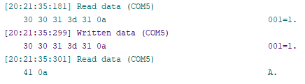
First, the command “001=1” is sent from the device to the Cockpit Hardware HUB. 001 is the ID of the first variable in the Arduino. In the Cockpit Hardware HUB, this is translated in the “Unique ID”, which is 003. That’s why if you put the LogLevel on High, you will see the line:
![]()
This command is then processed by the tool and is being sent by SimConnect via the Client Data Area to the WASM module (because it’s an L-var) who will then translate it in a command being sent to the FlyByWire A32NX using a set_named_variable_value from the Gauge API.
If all goes well, the result should be that the CSTR indicator of the EFIS_L on the FCU should lit up. Because of the change in indicator status, the value change will be sent through the Client Data Area back to SimConnect and will trigger the UI to show the value 1 for that variable (because it is RW). This value change of the variable with UniqueID 003 will also be sent to the Device with command “003=1”. The tool is going to translate the UniqueID in the DeviceID, which means that the command “001=1” is sent on the Serial USB (which can be seen in the screenshot).
The Arduino will receive this command and the CSTR LED will lit up. The Arduino will also send back an Acknowledge to the tool, which is simply the character “A” followed by a newline. This to indicate that the command has successfully be received.
Remark: All commands sent from the tool to the Arduino are being acknowledged by the Arduino by sending back the sequence “A\n”. If an Acknowledge is not received within 150 msec, the command is sent a second time. If that fails again, the tool gives up and goes to the next command. The next command will only be sent to the device after an acknowledge is received. This way of working avoids that the commands from the tool are sent too fast.
There is no acknowledge protocol when commands are sent from the Arduino back to the tool. I have not implemented this, but this is not that dramatic. First, the Arduino will only send commands if you take some action (push a button, dial an encoder, etc…) which is not 100 times per second, so the tool will definitely be capable of catching up. Second, if it really would happen, then in this very exceptional case, you will notice that your action has no effect, and you will try again.
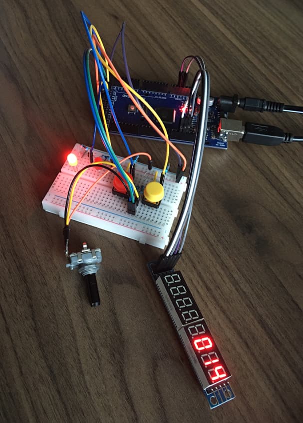
We can now also use the other button, and the Rotary Encoder. Below is a picture of the example at work.
4. Debugging your hardware
You can also debug your hardware without using the Cockpit Hardware HUB. You can use the “Serial Monitor” of the Arduino IDE, and enter the commands yourself to see the effect.
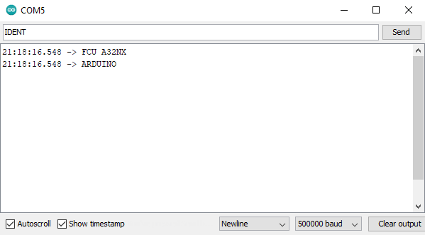
If you type “IDENT” followed by enter, you will see the below:
If you then type “REGISTER” followed by enter, you will see the list of variables that need to be registered:
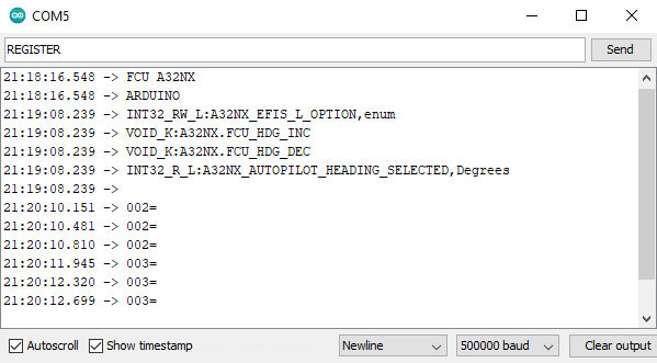
If you now turn the Rotary Encoder UP or DOWN, you will see the commands “002=” or “003=” (These are UP and DOWN events, and don’t need a value).
If you type the command “001=1”, you will see the CSTR LED lit up, and you will also see that the device returns the sequence “A/n” which is the Acknowledge being sent back.