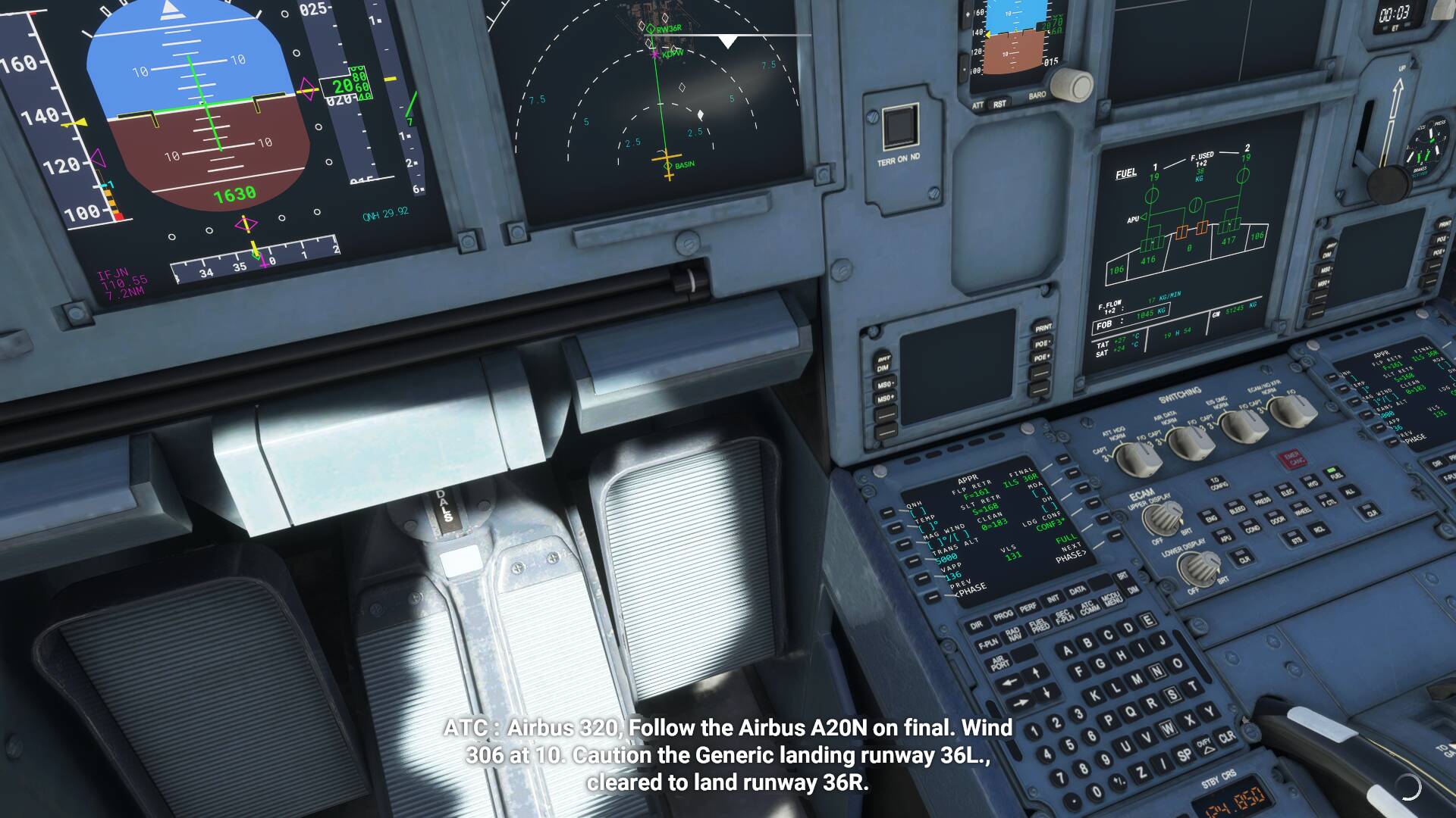
I noticed a disparity between the Vᴬᴾᴾ speed on the FMC and the managed Magenta speed when approach mode is activated on the default A320neo.
Could somebody explain the relation between the Vᴬᴾᴾ speed and the Managed speed on the default A320Neo. How does Vᴬᴾᴾ correspond with Vʳᵉᶠ, and are they interchangeble.
I did the approach by manually selecting the FMC calculated speed of 136kts. Was this right? So should I have let the aircraft reduce the magenta speed of ~120kts, despite this speed being below the Vls speed?
The default airbus is buggy and low fidelity, FBW is a significant improvement if you are on PC.
In the real world the magenta speed target on the PFD will not necessarily always be exactly the same as Vapp in the approach page of the MCDU (even when in final landing configuration) due to ground speed mini, but it will never be less than it as here.
The picture you’ve shown here is a result of a really fairly poorly modelled default aircraft. In so far as we can tell the 121kts is actually (almost) correct as it’s sitting (almost) 5kts above VLS on the strip which is what you would expect to normally see in light headwinds. Assuming FAC calculated VLS works correctly in the default aircraft (big assumption!) then ignoring any wind corrections VLS+5kts on the speed strip would be the correct speed to be flying.
Note that while the managed speed target would never be less than Vapp in the MCDU, on older airbii you can actually get indicated VLS between the strip and the MCDU to disagree if the entered weight is wrong as the FMGS calculates it assuming landing weight in cruise and using current gross weight after activation of approach phase. Conversely VLS on the speed strip on those older aircraft is calculated by the FACs using aerodynamic data (newer still
Use the FACS but calculate using weight data for consistency). The change means you wouldn’t expect to see a disagreement on a neo, but there is still fairly often a difference between VLS on the speed strip and in the MCDU on the older aircraft.
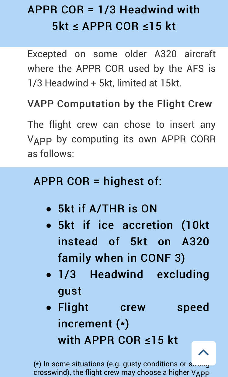
Vapp = VLS + 1/3 of the headwind components (limited to VLS + 5 as a minimum and VLS + 15 as a maximum).
For landing, VLS = 1.23x VS1G of the selected landing configuration (full or 3). VLS conf full = Vref and would be your base for any approach speed modifications due to failures.
The magenta managed speed target on the PFD should largely be the same as computed Vapp, but as mentioned you may see it higher at times due to the effect of ground speed mini.
Thank you for your very detailed response, I just assumed Vref and Vapp were interchangeable, so very insightful.
It also hit me that if you look at the MCDU in the image, the landing is configured for ‘CONF3’ not ‘FULL’, meaning that the Vapp and Vls speeds cited in the FMC are not compatible with the full configuration landing I was performing… alas I changed my Configuration to 3 and the figures all lined up.
Do you know if its possible to change the Config in the FMC of the default A320? Tried using the scratchpad to insert it, tried clicking on the key next to full but nothing. Appears as you say the A320 have exceptionally low fidelity, and it a shame the the FBW will never be available to Xbox user such as myself.
In the simplest terms, Vapp is basically Vref with an approach correction, which when everything is working and normal is based on 1/3 the runway headwind wind component (although always within the bounds of minimum 5, max 15). Wind isn’t the full story though, for example with failures there will be further speed corrections to take into account when working out the correct Vapp and pilots are also generally free to add an increment within that range if they feel it appropriate.
VLS does not always equal Vref however, as it is a context sensitive speed (eg the multiplier applied to VS1G changes in different configurations and stages of flight). In Conf Full however, VLS = Vref. In normal day to day operation of the Airbus Vref just isn’t really a commonly used term.
Actually It’s not immediately clear what you have selected in there to be honest - Again the systems just aren’t that particularly high fidelity, so the approach page doesn’t actually quite look like that… in real life it’s much more obvious which configuration you have selected in the approach page as the text will be larger for the selected config (and the landing memo will stop at 3 if conf 3 is selected). That said, the one with the star next to it shows it is selectable, ie not the current selection - While I can’t say for sure since the system just isn’t true to life, that suggests that you have actually got conf full selected in that screenshot.
No idea whether the config in the approach page is selectable in the default I’m afraid as I’ve uninstalled it! That said if you are clicking next to conf 3 (again with airbus user interface logic you would expect the one with the star next to it to be currently inactivate and ready for selection) and nothing changes then I guess not.
It is a great shame that FBW pulled the plug on the Xbox version. Here’s hoping one day it may return or someone else brings a better version to the platform. Asobo’s is nice to look at but that’s about where it ends unfortunately.
Is this true for the Airbus? Most of the turboprops I have flown used 1/3 headwind OR full gust up to maximum 15 kts.
Most jets I have flown used 1/2 headwind component AND full gust up to maximum 20 kts.
Edit:
Seems you are correct, 1/3 headwind without gust, guess the groundspeed mini calculation corrects for anything above? On the 737 there was a difference between A/T on or off for approach, with A/T on Vref + 5 was used as the A/T logic automatically corrects for any gusts, guess its somewhat the same here.
Yes, more or less… ground speed mini is added to Vapp so end result is similar but obviously much more dynamic. Worth noting that the NEO provides a significantly smaller groundspeed mini increment than the CEO however as it was reduced from simply being current headwind component - tower headwind component down to 1/3rd of it.
For the NEO:
GROUND SPEED MINI FUNCTION PRINCIPLE
The objective of the Ground Speed Mini function is to take advantage of the aircraft inertia, when the wind varies during the approach. This objective is achieved
by providing the adequate indicated speed target (i.e. the managed speed target represented by the magenta triangle). When the aircraft flies this indicated air
speed target, the energy of the aircraft is maintained above a minimum level ensuring aerodynamic margins versus stall.
During the approach, the FG continuously computes the managed speed target in order to take into account the gusts or wind changes
VAPP COMPUTATION
The MS computes the VAPP, and displays it on the PERF APPR page. The VAPP computation takes into account the tower headwind component. VAPP is
computed as follows:
VAPP = VLS+ 1/3 of the TWR HEADWIND COMPONENT, or
VAPP = VLS +5 kt, whichever is the highest.
Note: “1/3 of the TWR HEADWIND COMPONENT” has two limits:
0 kt as the minimum value (no wind or tailwind)
+15 kt as the maximum value.
The flight crew can manually modify the VAPP and MAG WIND values on the PERF APPR page.
MANAGED SPEED TARGET COMPUTATION
The FG continuously computes the managed speed target that is equal to VAPP plus an additional increment. This increment takes into account the headwind
variation during the final approach.
Managed speed target = VAPP + 1/3* (current headwind component - tower headwind component).
The managed speed target has the following limits:
VAPP, as the minimum value
VFE next, in CONF 0,1,2,3, VFE-5 kt in CONF FULL, as the maximum value.