Airspeed vs Groundspeed

I might be wrong, but there’s always 1kt of wind usually in MSFS, even at its lowest
Havent test 0wind in a long time though

I’ll test on my side

Absolutely nothing to see here folks. Here is approx the same shot as the original, but in dev mode with the debug airspeed window showing so you can read all the airspeeds:

Note that the true airspeed is equal to the ground speed (no wind). Also note that there is only a one knot difference between the true airspeed and the calibrated airspeed. This is also correct. See this screenshot showing the conversion between KTAS and KCAS (within roundoff):


Last, but not least, notice the relatively large difference between KIAS and KCAS. This is due to airspeed indication error. Is this magnitude correct? I couldn’t tell you. But, I can tell you it is exactly what is coded in the cockpit.cfg file for this airplane (Cessna 172SP with Garmin 1000):
Screenshot (1130)
The first value (1.1236) is a scalar. The 2nd value (-13.4) is an offset. Apply the offset first to KCAS, then the scalar, to get KIAS. In other words, take 85, subtract 13.4, then multiply by 1.1236. What do you get? 80, which is the indicated airspeed.

No “overzealous density error calculation,” whatever that may be, or any other error. MSFS SU5 does airspeed conversions correctly (except for the very small areas where the atmospheric parameters are still a bit off).

1 Like

Thanks Awareplot - the dev mode readout is helpful.

In which case it appears that instrument/position error are calculated incorrectly for the C172S.

The difference between KCAS and KIAS should not be +5kts at 80KIAS:

Is someone here surprised…

I think you mean it is not represented accurately in the cockpit.cfg file. The airspeeds are calculated correctly for the given inputs. Since you have the data, you can now modify your airplane and give it the correct indicator error inputs.

1 Like

With utmost respect, the .cfg file is a direct function of the simulator and should not require modification to calculate the correct KIAS.

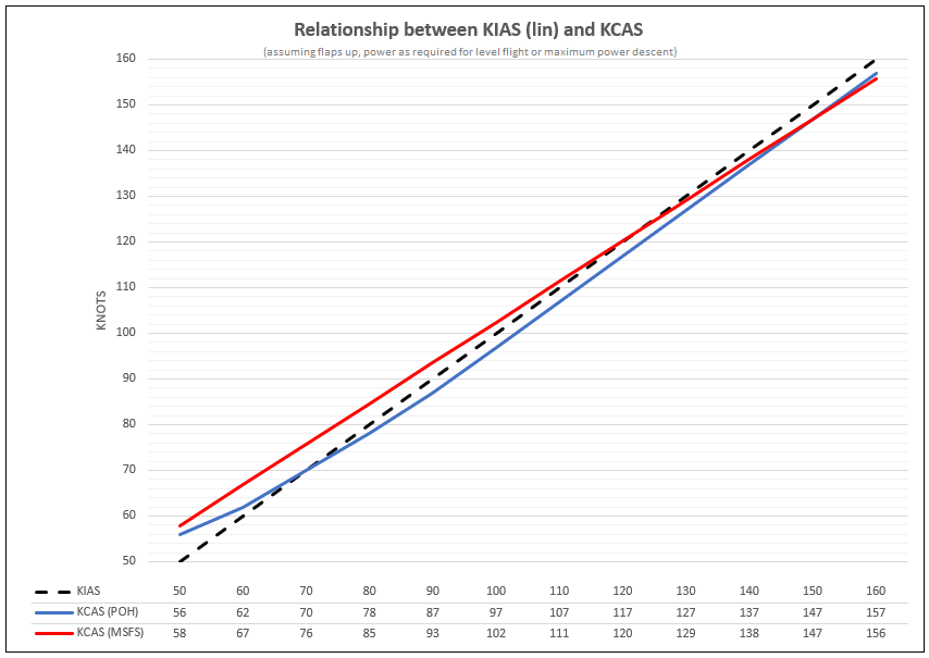
Furthermore, the linear function of an offset and a multiplier fail to accurately model the non-linear relationship as per the Cessna POH, as below:

That said, I am of the opinion that Asobo should focus on accurate flight/atmospheric/world models and leave [accurate] aircraft to third-party development, so it is positive to hear that the environmental aspects appear to be correct.

The problem is that it can’t easily be “calculated” by a fixed conversion formula (offset and multiplier) because the IAS/CAS relationship is non-linear.

“Instrument” error really would not be something that would likely be simulated in something like MSFS. It is simply a measure of a specific make and model airspeed indicator’s intrinsic accuracy with a known input pitot pressure. This can easily be measured on the ground on a test bench, (or in the aircraft) using a calibrated pitot-static pressure test set.

Older mechanical airspeed indicators can have substantial instrument error at the low end of their operating range, and much less at higher speeds. Modern air data computers which use solid state pressure transducers tend to have no “instrument” error whatsoever for raw dynamic pressure at any point in their normal operating range.

I suppose that an advanced add-on like the A2A series of GA aircraft in FSX and P3D might indeed simulate the known “instrument” error of a specific model of analog airspeed indicator.

“Position” error is another matter. That is caused by non-linear variations in sensed static pressure caused by airflow across the static port.

In a real aircraft, static source error can vary significantly with changes in airflow across the static port at various airspeeds and (especially) with changes in the angle of attack. The amount of error depends on the specific airframe, and exactly where the static port is located.

A digital air data computer designed for use in high performance jet aircraft will contain lookup tables to correlate IAS to CAS, and also to correct indicated altitude for airspeed.

This latter correction is especially critical in an aircraft certified for operation in RVSM airspace. All DADC’s in high-performance aircraft take pitot pressure and static pressure as inputs, along with air temperature. Most (but not all), also take an input from the angle of attack sensor(s).

The IAS vs. CAS and altitude correction lookup tables will not come from algorithms, but from data gathered during extensive flight testing.

Other air data parameters such as TAS and Mach will indeed be calculated by formulae, using CAS derived from the lookup tables.

I assume that a custom FDE for an advanced simulator add-on could use similar lookup tables to give correct CAS results across the entire flight envelope, rather than relying on a fixed conversion formula.

2 Likes

Thanks HalberQuacky,

I imagine this could be simulated formulaically or via lookup table, or a combination of both. Either way, as you say, instrument and position errors are extremely airframe/equipment dependent and I certainly wouldn’t expect Asobo’s models to be of such high fidelity. However I hope that this is able to be corrected by third-party developers, despite Asobo wanting to keep the flight model under wraps.

It has been a long time since I’ve used FSX but I don’t remember there ever being such a significant difference between TAS/CAS and IAS at ‘normal’ angles of attack. It would make for an interesting test if that is potentially where this code has come from.

Me thinks you’re making this much too difficult. We’re dealing with a simulation, not a real airplane/atmosphere. Indicator and position error must all be added; they do not exist in the simulator like they would in real life. There is no actual pitot tube, nor any static source that may not read the exact static air pressure. For airplanes with digital air data computers, there is no correction needed in the simulation. CAS is calculated from TAS, and IAS is made equal to IAS. No need for simulating the actual lookup tables unless you for some reason wanted to simulate some residual error that may exist after using those tables (due to airframe or static source accuracy variability or something).

The instrument error simulation provided for by the MSFS (and previous FSX) config files are simple linear relationships. Developers have the option of going beyond that to program their own gages to include more complex relationships (as you assumed).

I don’t understand the desire of some to want to conduct more “tests” of this sort. It is all very straightforward and documented in the FSX SDK.

The big advance in MSFS SU5 is that the conversion between TAS and CAS, which has been incorrect since FSX days, has been fixed. None of these other aspects being discussed (airspeed indicator error or static source error) have been changed or need to be changed.

5 Likes

I completely agree.

There was lots that I didn’t know there, thanks.

I think we’ve more than answered the OPs question.

2 Likes

As has the relationship between CAS and Mach at a given pressure altitude. That has been wrong (at altitudes above ~FL250) since FS9, and every developer of complex airliner add-ons in FSX and P3D (that operate at the flight levels) has had to write a custom conversion to derive displayed IAS from the Mach sim var, rather than using the native IAS sim var directly. I was pleasantly surprised while doing some test flights between FL300 and FL 390 in SU5 HF2 to find that long-standing bug appears to have been fixed.

2 Likes

Yes, that’s the same bug.

I think a multi-point curve would be a good improvement in the SDK, and here is why I say that:

Imagine you are trying to model a C172 to behave according to POH values. You setup the airspeed_indicators entry to have KIAS and KCAS be almost the same at cruise and approach speeds as per the POH. Then you tweak the flight model until the stall speed is according to POH; the aircraft stalls with full flaps when the airspeed indicator reads 40, just as it should. Then you fly the short field landing at 61 knots on the airspeed indicator and the behavior is way off; the aircraft just floats and floats and floats.

Why? Because without modeling the nonlinear divergence between KIAS and KCAS at very low airspeeds the airspeed indicator is within a couple knots of KCAS even at low speed, and when you got the aircraft to stall at “40 knots” you ended up making the stall speed 8 knots too low (close to 40 KCAS instead of 40 KIAS/48 KCAS). The effect is the aircraft feels like you flew the approach way too fast, and the landing behavior does not feel like it should. I think it is quite common for MSFS aircraft to float more than they should so this seems like a general problem. If you make the stall speed 48 kts on the airspeed indicator instead then that is obviously quite a surprise when you do stall training so that is not a good solution either.

My point is that it is not possible to get the C172 indicated stall speed and the behavior at the correct indicated landing speed to be simultaneously correct without modeling the nonlinear relationship between KIAS and KCAS at very low speed, at least not without workarounds like messing with flaps drag which has other bad effects (such as unrealistically low rate of climb with flaps extended, also a common problem with MSFS aircraft).

1 Like

I don’t understand. I thought the IAS/CAS difference it simulated in MSFS?

The main reason for the excessive float is IMO the basic omision that the stall AoA decreases with flap angle and hence an incorrect lift/drag curve.

Another one is the lack of a slats simulation. It’s most likely the only current sim which doesn’t do that.

It is simulated, but as I read the posts by @AwarePlot117729 and @HimmelLotse (see the plot a few posts up) it is modeled as a linear relation with just two parameters, offset and multiplier. Whereas the real-world relationship tends to be highly nonlinear, especially at low speed for some aircraft, again see the plot in @HimmelLotse 's post.

For example, looking at that plot, 60 KIAS corresponds to 62 KCAS in the POH but 67 KCAS in MSFS. If the stall speed is 48 KCAS in both cases (note the red and blue speed curves converging towards the stall speed to try to get that speed accurate) the sim aircraft flying at 60 KIAS is 40% above stall speed which is way high as a short field landing speed, whereas the real aircraft would be 29% above stall speed and therefore float much less.

I am sure there are other flight model issues that play a role as well, but even if the flight model was perfect and the enforced linear IAS/CAS relationship was the only problem in the entire sim it would still not be possible to get landing behavior correct without introducing other problems, for the reasons I mentioned above.

It’s a strange offset Asobo has chosen. I’ve always set mine so that it matches the difference in the important approach & low speed regime.

1 Like

Yeah that would make a lot more sense… Guess that makes it hard to match POH performance at cruise? I have had some simulator aircraft (maybe not one of yours, I would not know) where calculating KTAS from KIAS using the E6B and compensating for wind gives a totally different value for ground speed from what the GPS and DME are saying, maybe this issue has something to do with it…

Flight simulation is complicated.

Since you are not cruising at SL and usually TAS is used for performance I’ve always considered the approach case more important

The takeoff performance case is even more important.
A 5kts error at these low speeds severely affects the required acceleration and distances.

Agreed, it is complicated.

2 Likes

In the case of the 172 specifically, the IAS/CAS relationship will be different between an older aircraft with a mechanical analog airspeed indicator, vs. a newer model with a G-1000.

With the older analog instrument, much of the difference at the low end of the scale is from “instrument” error - the pressure bellows and associated gear work in the indicator is simply not very sensitive at low pitot pressures. The G-1000 uses a dedicated air data module with solid state pressure transducers, which is much more linear.

“Position” error will be the same in either case, as the static port is in the same location on all 172s, (on the side of the forward fuselage just aft of the engine). If the aircraft came from the factory with an analog airspeed indicator, the IAS/CAS tables in the aircraft flight manual (AFM) will be valid for the analog instrument. If a G1000 was later installed as an upgrade, the approved flight manual supplement for the G1000 will contain a new IAS/CAS table.

If it is a newer 172 that came from the factory with a G1000, then the IAS/CAS tables in the main AFM will be valid for the G1000.

Interestingly, in the US, there is no FAA regulation that requires that an airspeed indicator ever be tested for accuracy. FAR 91.411 does require that the altimeter be tested every 2 years for accuracy - but that is only required if the aircraft is used for IFR. If a particular aircraft is used strictly for VFR, even the altimeter calibration never has to be tested on an ongoing basis.

When doing a 2-year altimeter/transponder recertification on a GA aircraft like a 172, I always check the accuracy of the airspeed indicator even though regulations do not require it. I had one customer with a 1966 Piper Cherokee 140 who was strictly a VFR pilot, who finally decided to have his altimeter recertified.

In the course of doing the tests, I found the airspeed indicator read 10 knots low across the entire operating range. It may well have had that amount of error for many years. The customer opted to simply leave it that way. He had owned the aircraft for 25 years, and was used to flying it with that particular airspeed indicator.

An error on the high side would have been of more concern - but even there, under FAA regulations, I cannot declare an aircraft un-airworthy for an inaccurate airspeed indicator. If the altimeter does not meet required accuracy specs, I can require it be replaced before signing off the logbook, but not for an inaccurate airspeed indicator.

5 Likes

So I use this page to calculate TAS from IAS. Even at 2000ft there will be a difference.

csgnetwork.com/tasinfocalc.html

Here it is calculating 74 IAS would be 77 TAS