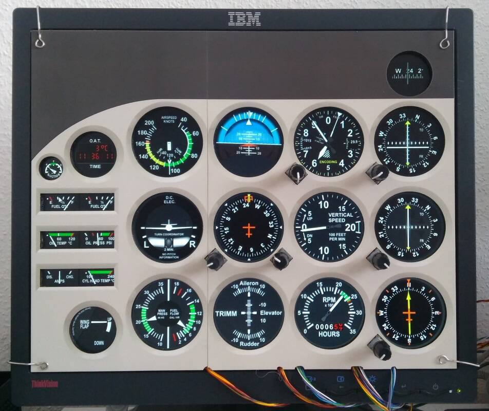
Many years ago I was involved in the development of the ITRA devices. Now I have started again to deal with flight simulation equipment in my spare time. My goal is a small cockpit for a C172. All input devices, such as the avionics and encoder controls of the cockpit and the switch controls will communicate via network with the SimConnect of FSX and FS2020. Modified ITRA panel software, also connected via network, will be used as cockpit instruments.
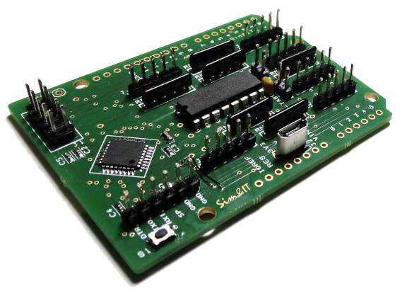
The avionics assemblies are started as single assemblies (5 cm x 8 cm) with as many purchase components as possible. So the Arduino Pro Mini is plugged onto a socket
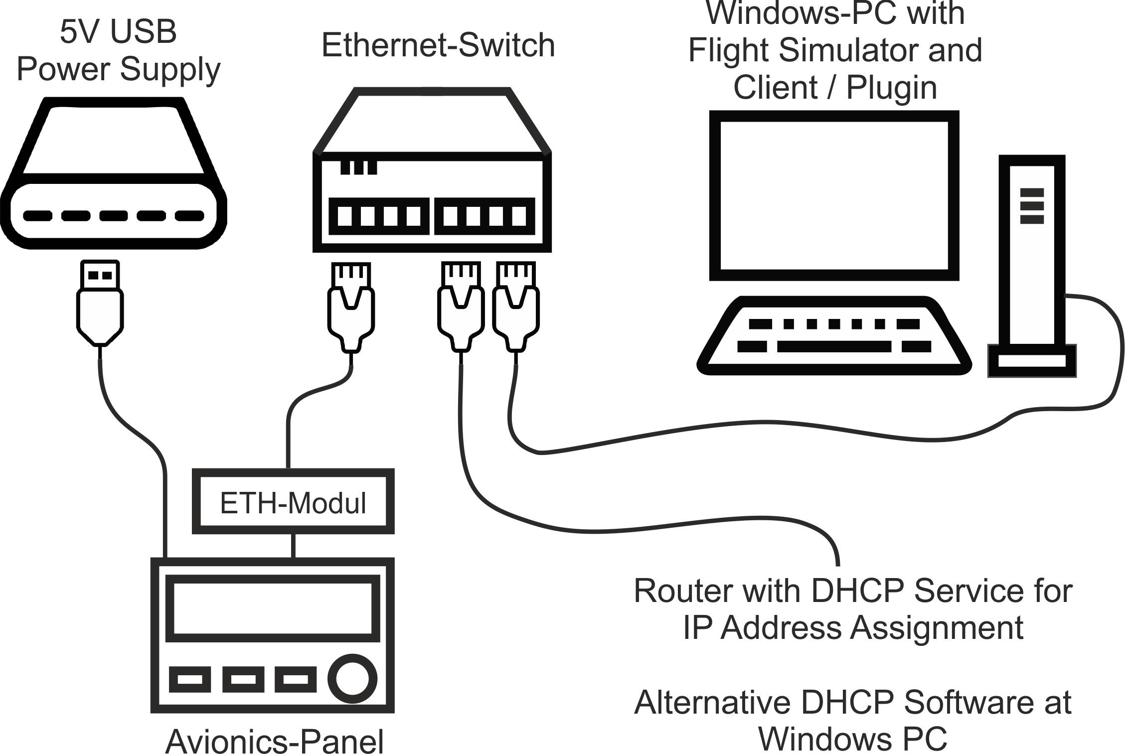
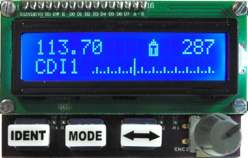
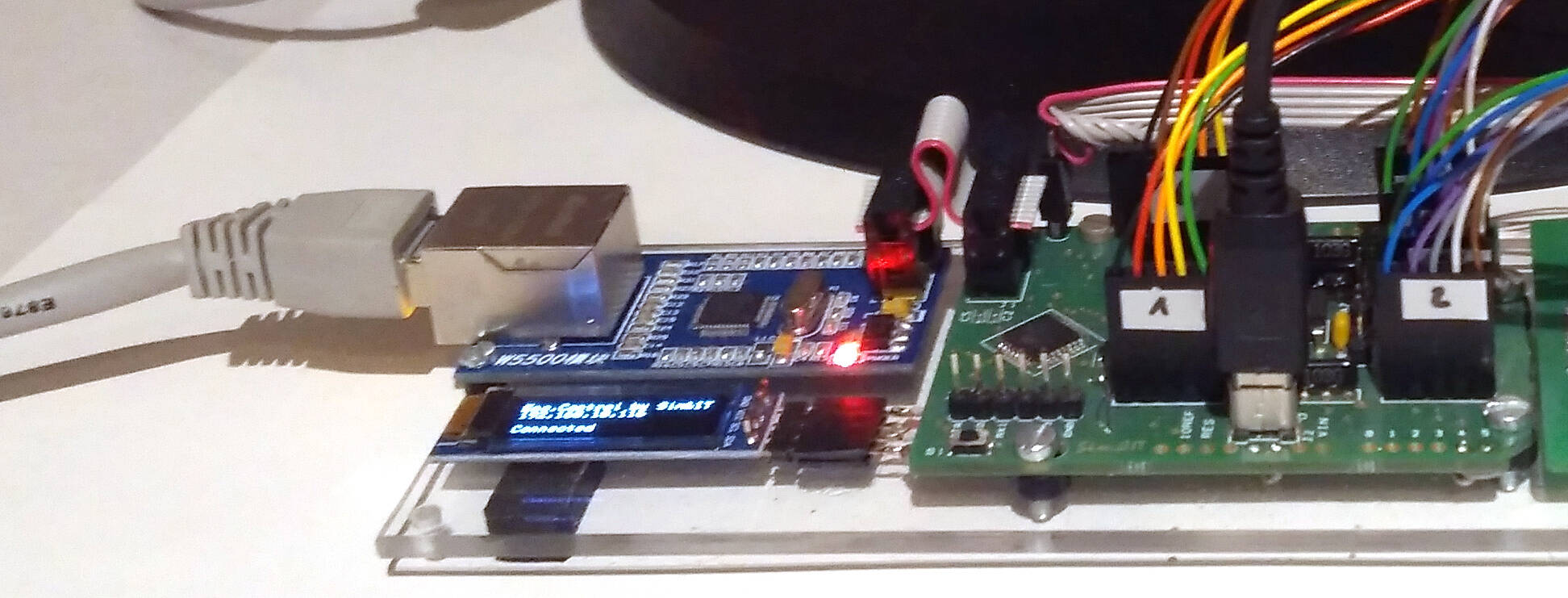
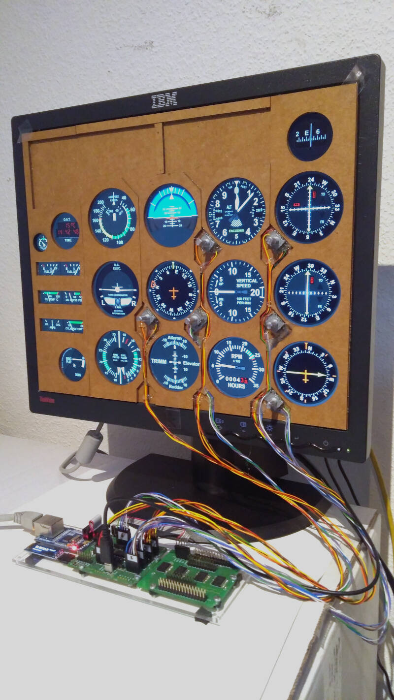
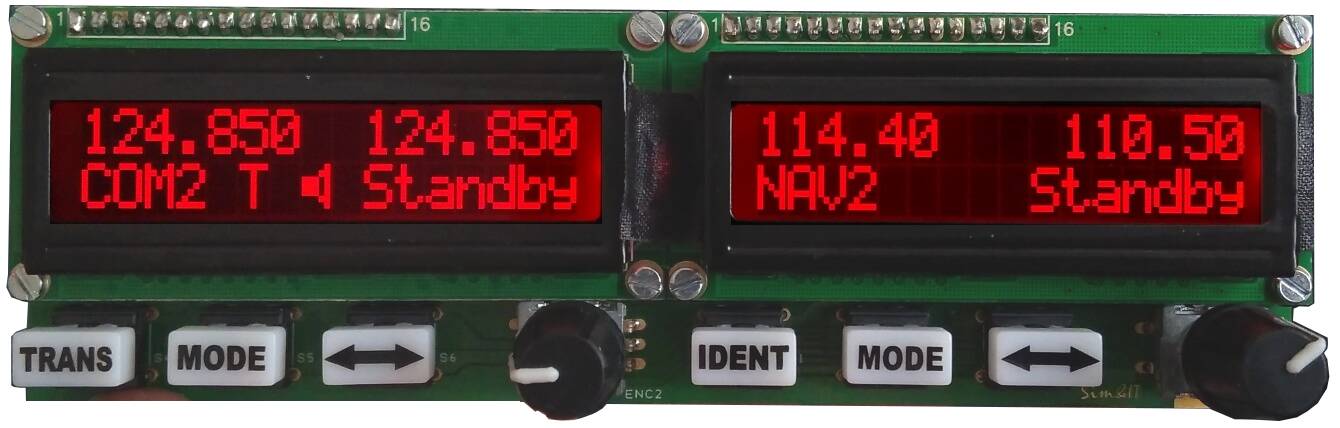
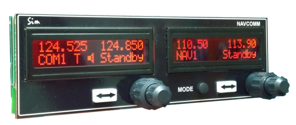
The COM instrument provides the active and standby display. The NAV instrument has additional modes like CDI, Bearing to, Radial from, DME. There is also an ADF and an XPNDR module. The function of the module can be changed at power on with the keys. The connection to the network is simple. The module gets its IP address with DHCP from the router. Module and Simconnect client find each other automatically. Every Module has an unique MAC-address communicates over a unique UDP-Port, so it is no problem to run all modules together in the network.
The hardware can be built by yourself. More information is available on my wiki page. Sim&IT Wiki Page
I offer a license for SimConnect client for purchase, this includes the possibility to get the Arduino sources. The client runs 10 minutes in Demo mode, COM1 without licence.
In the next post I will write about the Encoder Control
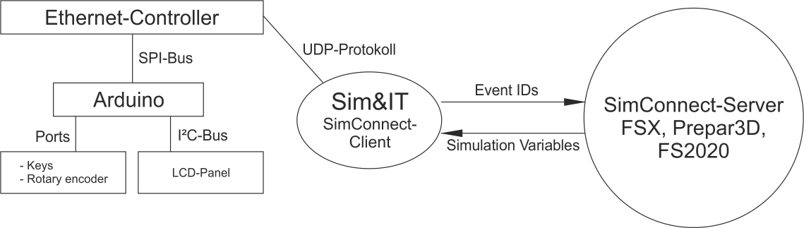
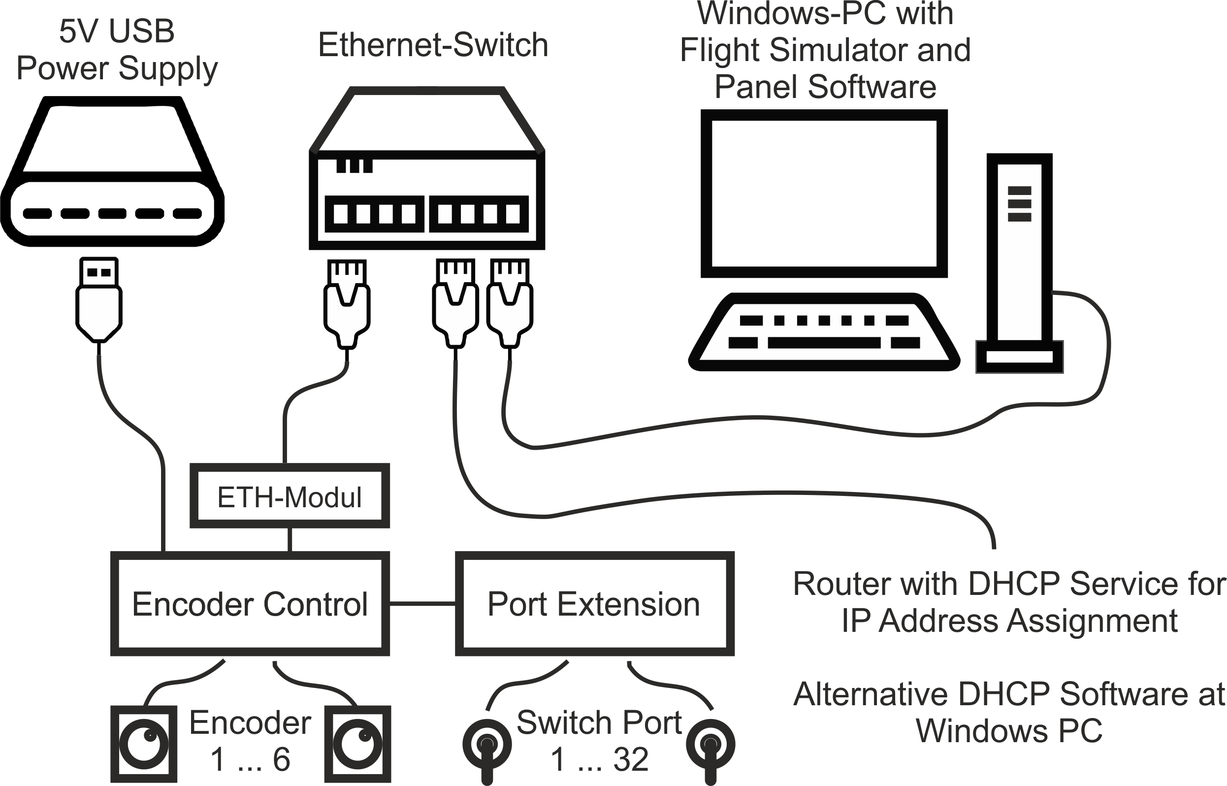
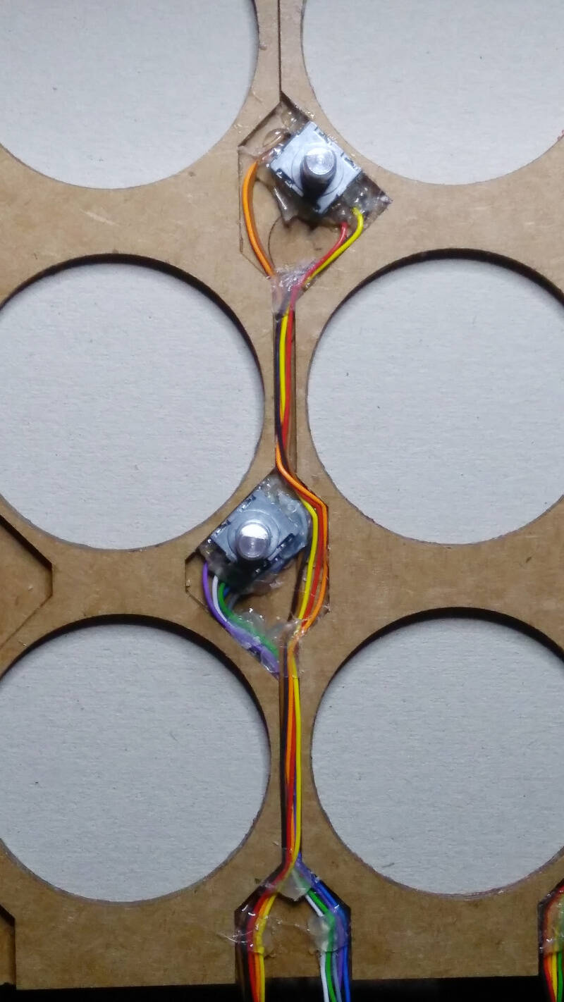
EncoderControl works in the same way as Avionics. An ATmega328 is used, which is programmed with the Arduino IDE. The SPI lines are needed for the Ethernet controller, and the I²C bus for extensions. For 6 encoders, 12 inputs of the ATmega are used. This decodes the pulses and thus also the direction of rotation of the encoders.For the 6 push buttons, an I²C port expander is used, which reports a push on the encoder axis with the interrupt line.
The video shows the setting of the OBS1 via the EncoderControl and the visualisation on a panel PC, which is also connected via network.. Push button switches between normal (+1 deg) and fast mode (+5 deg). The panel PC runs software that was formerly developed at ITRA and has been extended by some instruments.
Additional information about the EncoderControl you will find at my Wiki page and also about the cockpit PC, but this only in german.
I have also tried LC-dot-displays with red background for the avionics. But these displays have a very limited lateral viewing area. The contrast decreases significantly.
Interesting project! Building something like this for myself right now. Did I get this right - you are selling the software that runs in the Arduino?
Love the red-on-black LEDs even though they are not good for lateral viewing. They look more like the real thing.
The software consists of two parts, the Arduino sketch and the SimConnect client that runs at the FS PC. The SimConnect client runs for 10 minutes in demo mode, COM1 without limitation. A licence key is needed to unlock the software, which I sell. The source file for the Arduino is included. All single Avionics are using the same sketch, the function is defined and stored at power up/reset with the three keys.
The circuit boards can be ordered from Aisler.
The hardware with the Arduino Pro Mini can be made by yourself. The links, schematics and parts list are on my wiki page. The link to the client setup can be found at the section Communikation Software.
I only found the red displays without the I²C extension, but the I²C extensions for the 16x2 displays can also be bought separately.
Looks Great! I am Using something similar but with CAN Bus. Its a Little Bit easier to implement imho, cheaper and also can work in a big Networkw without switches.
Thanks, but I think you also need an extra driver circuit on the PC and on the Arduino for CAN. And, I know a lot about Ethernet. In terms of price, the Ethernet extensions for the Arduino are around 6€. A Fast Ethernet switch costs about 20€. That is an acceptable price for me. The Ethernet connection is available in the PC and the slim PC for the TFT software is also connected via Ethernet. So I have connected all the cockpit elements via Ethernet. With the Ethernet modules I use, I also have galvanic isolation of the devices from the PC and from each other. CAN is somewhat more familiar to me from automation as DeviceNet. But you need either a T-piece or an input and output on the device.
The complete hardware of the avionics, rotary encoder and switch control is not a comercail project, all the parts are possible to built by yourselfe. All schematics, PCB designs and BOM are freely available, the Arduino code can be freely requested. And I think that 15€ for the SimConnect licence should not be seen as a commercial offer, but as a nominal fee, so that others do not make a business out of it. So I think, it is not a mainly commercial advertisment. I do all of the flight simulation in my spare time, it is not my main business.
The rules seem to state “is not to be used for any non-MSFS related businesses”. Since this is related to MSFS, I hope it can stay up. 15€ really is more of a nominal fee IMO.
I’ll continue here, although the discussion about whether or not I’m allowed to do this is not yet over. There was a comment from TFEV1909, now deleted, that I was breaking forum rules by not providing the code for the SimConnect clients, or the clients for free, and thus advertising my part-time job.
I will limit myself to building the units that I build only for myself.
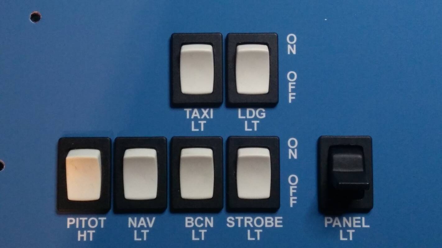
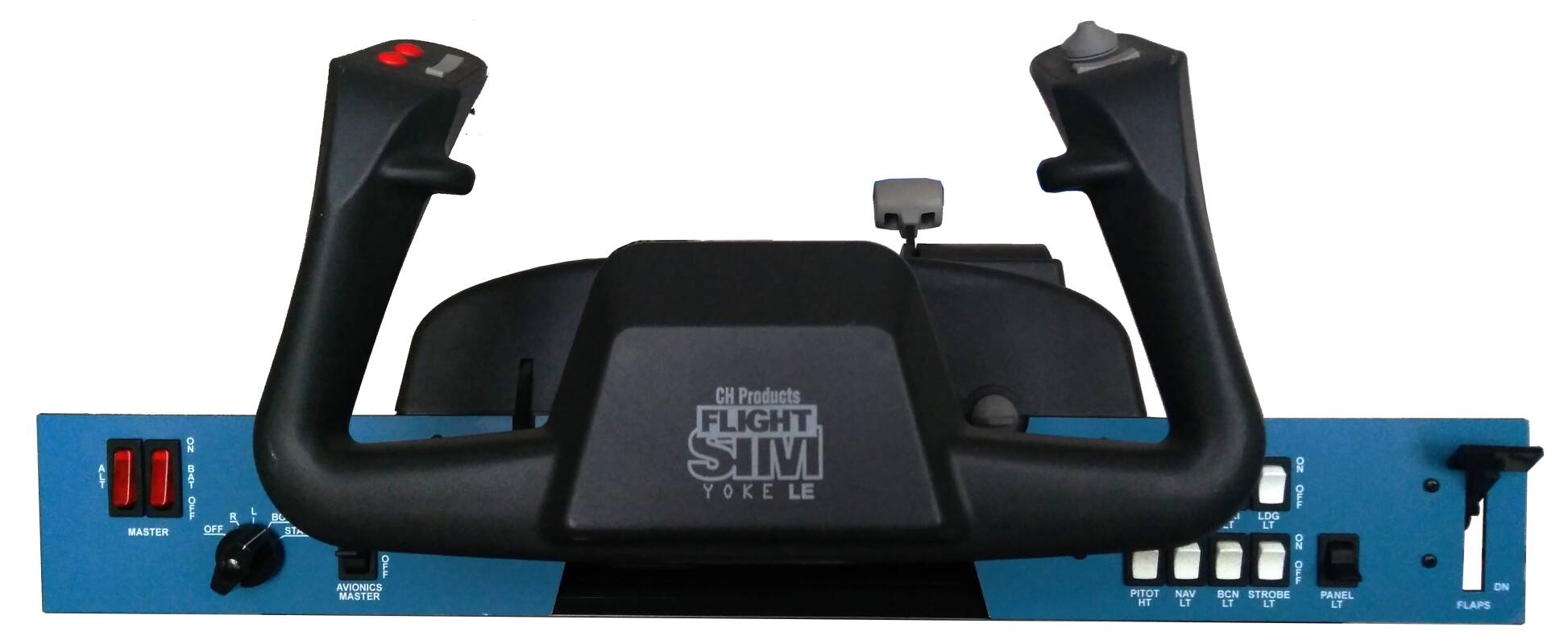
The next stage is the switch unit. Since I had decided on the look of a C172 Skyhawk XP, I needed white light switches in a black frame. I put these together from black and white rocker switches.
I then used the other toggle switches in a similar design, i.e. square to snap into place. The frame was covered with photo paper.
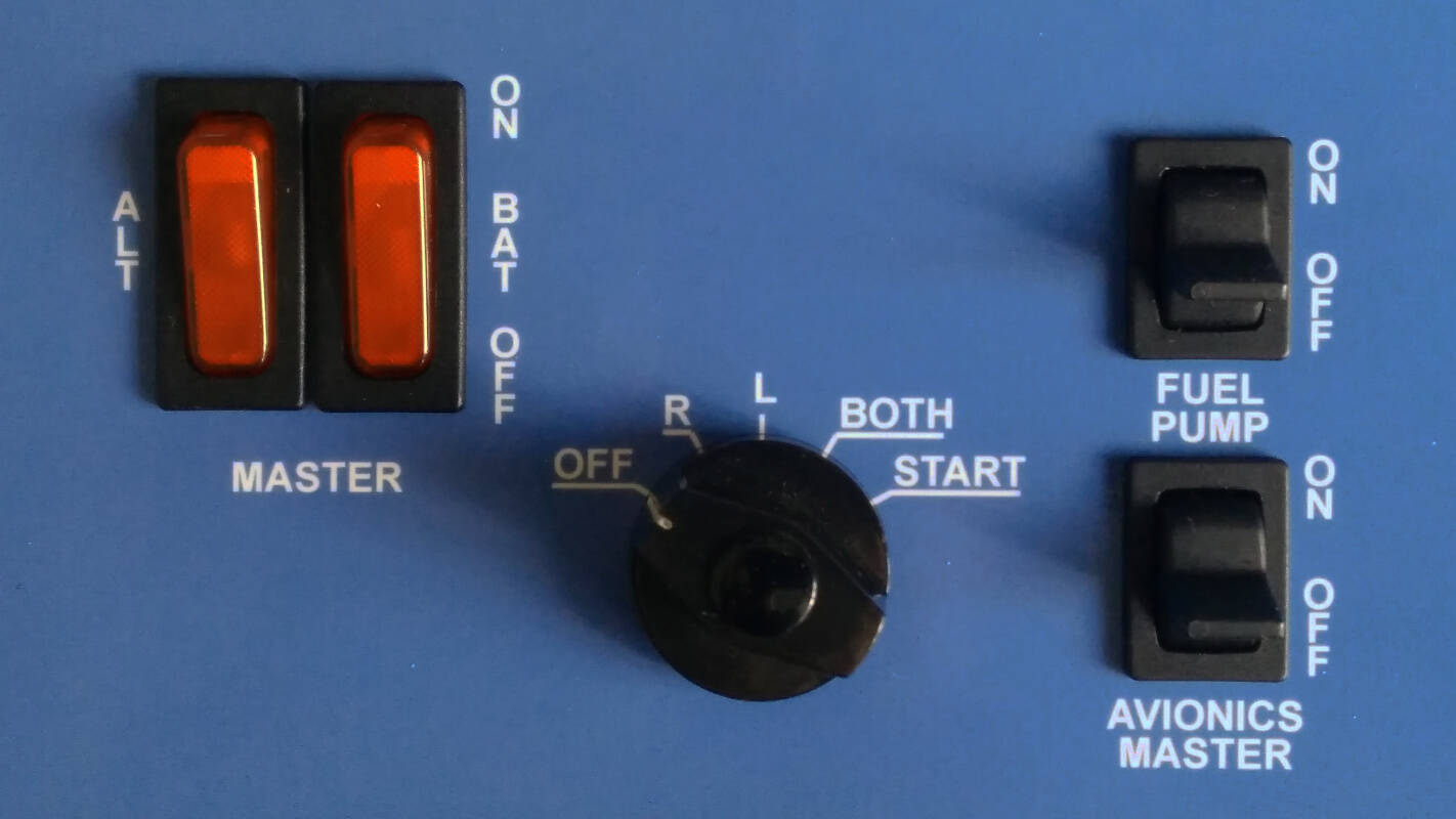
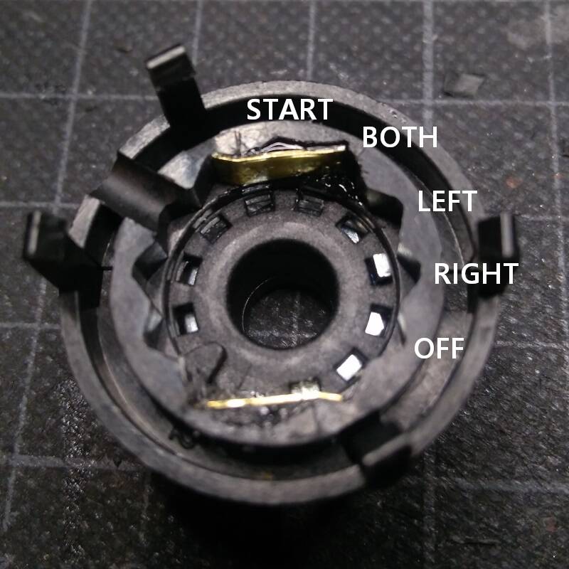
The main switches and the starter are then located on the left-hand side. I couldn’t find a suitable component for the starter, so I modified a rotary switch so that the last switch position does not engage but springs back. To do this, I took apart a 12-position rotary switch and bridged the detent at START with two brass plates. The springs and balls inside the rotary switch then spring back to BOTH. The rotary switch can be limited to any number of positions with the enclosed disc with one tooth.
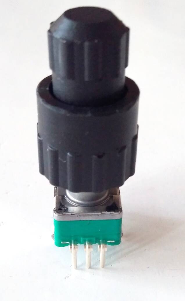
I am starting to modify the Avionics circuit boards to use a single axis encoder as described above or a dual axis encoder. An Alps EC11EBB24C03 is then used. It is significantly more expensive than a single axis encoder. For the buttons, I found a template for 3D printing that fits well on the encoder.
Of course, a second Arduino sketch must then be written. The identification, which is exchanged when the connection is established, will be used to differentiate in the SimConnect client.
For the version with dual encoders, the inputs of the Arduino are only sufficient for connecting 4 buttons, which are then the two SWAP buttons, the MODE button on the NAV and the push button on the rotary encoder. For this version I also used LC displays with a red background. These displays have a very limited lateral viewing area. The contrast decreases significantly. But it looks more realistic. Everything was mounted on a front panel onto which a printed photo paper was then glued.