Button Box: G1000 / Autopilot / Lights / Gear / Flaps

Wanted to share some experiences from a project that I recently completed.

It’s a button box that’s designed to cover the functions I use most frequently in flight, focusing on those things that can’t be done very well with my Stream Deck. So there aren’t that many actual buttons on this box; instead, I’ve got a lot of rotary encoders as well as switches whose position indicates the status of a given system.

The left-hand section vaguely mimics the knobs you would see on a G1000, but these functions can obviously also be used with other aircraft. The middle section has autopilot controls at the top and external light switches at the bottom. The right-hand side has controls for the gear, parking brake, and flaps.

There aren’t any displays – again, I figured I could do the same thing better with a Stream Deck – but I did want to have gear lights next to the gear switch.

In terms of components, I used Elma E37 encoders for the dual rotary knobs, CTS288V encoders for the single knobs (speed and heading), an Elma E33 encoder for the vertical speed wheel and an Alps Alpine RKJXT1F42001 combined rotary encoder and joystick for the range / pan knob. There are also various switches as well as a few LEDs. An Arduino Mega 2560 Rev 3 serves as the interface board, and it’s hooked up to MSFS using Mobiflight.

I designed 3D-printed components for the range / pan knob and vertical speed thumb wheel, as I was unable to find suitable existing components for these. I also 3D-printed brackets to attach the encoders for the range / pan knob and vertical speed wheel to the panel. As I don’t own a 3D printer, I had the parts printed commercially by FAMA3D, which offers 3D printing services using the Multi Jet Fusion (MJF) process. I was pretty satisfied with the surface finish and durability of the resulting parts:

Unlike the Fused Deposition Modeling process used in most 3D printers available for home use, MJF has the advantage that it can print parts of almost arbitrary geometry, including overhangs; this came in useful for the 3D parts I printed for the case, which I’ll talk about in a moment.

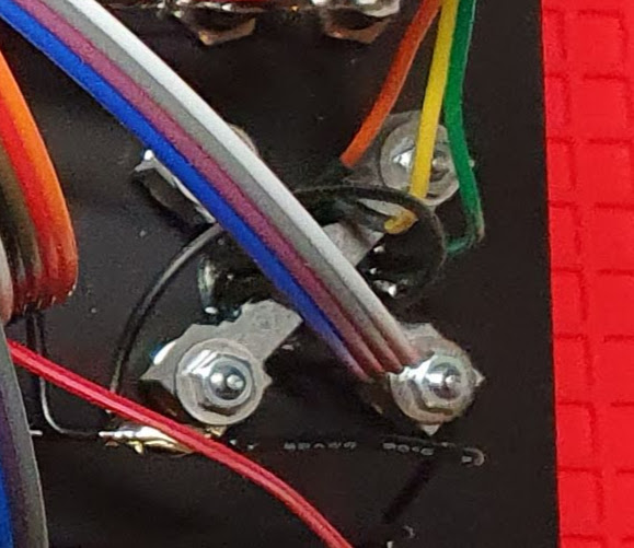
Here’s what the panel looks like on the rear:

You can see the 3D-printed bracket for the vertical speed wheel near the top left and the bracket for the range / pan knob near the bottom right. (Please don’t look too closely at my soldering – I know I need a lot more practice. :open_mouth:)

The front panel as well as the other aluminium panels that make up the case were manufactured by Schaeffer AG. They’re not cheap, but I can’t fault the quality and precision of the finished parts. The panels are connected using more 3D printed parts, as can be seen in the first photo.

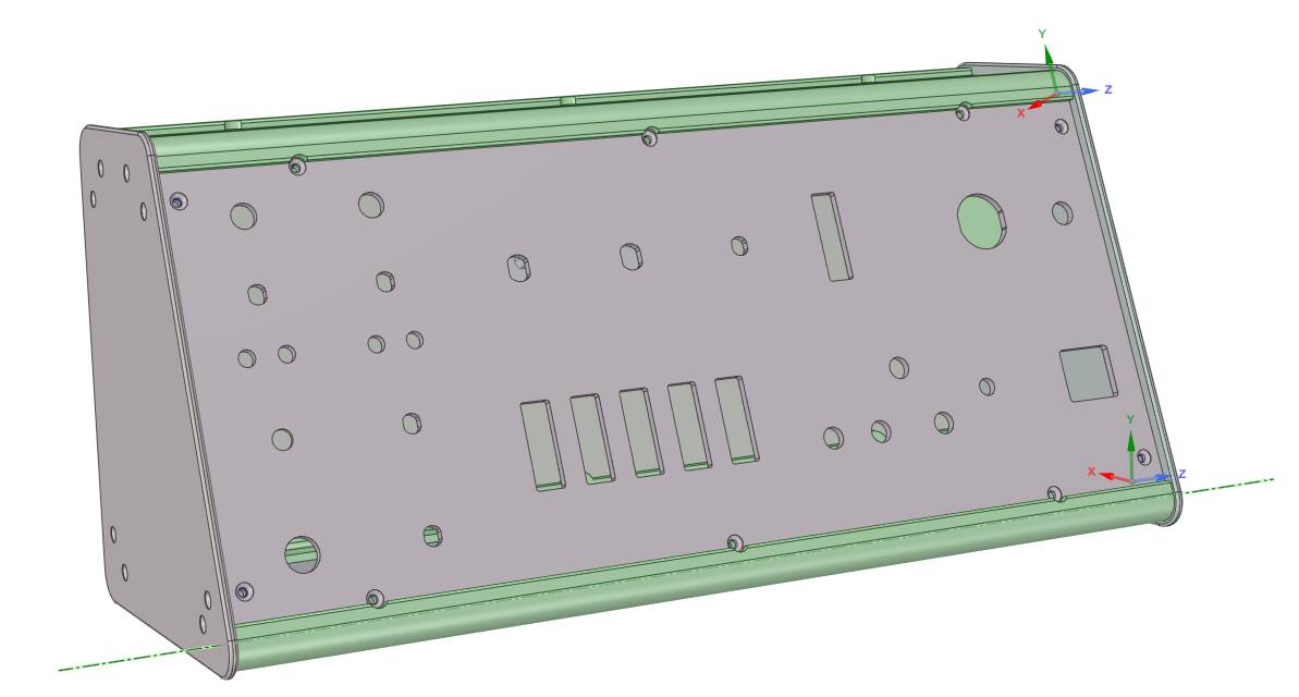
I designed the first 3D printed parts using Tinkercad, but it was too limited in its capabilities for the case parts. For these, I switched to DesignSpark Mechanical. This also came in useful for checking that all the parts would fit together as intended:

Lessons learned:

  • I didn’t give enough thought to how I would assemble the case. As it turned out, there were some screws in the middle of the case where it was extremely tricky to get a nut into the right place on the inside of the case.

  • The MJF process produces quality parts, but the finished parts will still have some dimensional tolerances, and this became particularly noticeable for the long case parts. I thought I had taken this into account sufficiently by making the screw holes slightly elongated, but I still ended up having to enlarge them using a file. The parts also ended up being slightly longer than the aluminium panels, so I had to file them down. Still better than having the parts end up being too short.

Happy to answer any questions!

6 Likes

Awesome… Looks great.

This is absolutely fantastic! Congratulations on this build. I am totally new when it comes to this stuff so apologies in advance for the silly questions:

This is very helpful for me because I am in the process of building something similar. I am particularly interested in the RKJXT1F42001 Range / Push pan knob which is absolutely fantastic.

  • Could you explain the wiring to me? I have a Leo Bodnar BUO836X board with 6 inputs for the joystick + push button. Could I utilize these for the pan + push functions on this knob? I imagine that the encoder functions of the knob will need to go into 2 button inputs on the Leo Bodnar board? Is that correct?

  • Would it be possible for you to share the files required for 3D printing the Range knob? And is the bracket that you have printed for this knob a necessity? Or is it a quality of life thing? And after 3D printing the knob, you painted it black?

  • Can you explain a little more about the switch used for Flaps and the knob that you printed for it? It’s awesome!

Thank you so much for your help and well done again on a wonderful build!

1 Like

If you want to use all of the functions of the knob, you’ll need 7 inputs:

  • 2 for the encoder
  • 4 for the joystick directions
  • 1 for the push button

Another thing to be aware of is that when you move the joystick left / right / up / down, it activates the “push” switch at the same time – so you’ll need some logic (in hardware or software) to make sure you trigger the “push” function only if none of the four joystick direction switches is closed. There’s a table here that illustrates this (scroll down to “Output Relation Chart Between Lever Position and On Position”):

I believe the Leo Bodnar joystick boards themselves don’t allow you to implement this kind of logic, so you’d have to do it either a) in hardware, b) directly in the sim (if it allows that), or c) using some third-party joystick software that allows you to implement this logic.

Best idea might be to order just the encoder, connect it up to your interface board, and do some testing before you commit to a design.

Sure, I’d be happy to! Can we coordinate by PM? Only reason is that I’d like to know who is using the files and how they’re using them.

Unlike most of the other switches and encoders I used in this project, the RKJXT1F42001 can’t be screwed directly to the front panel – it’s designed to be soldered onto a PCB. As I was going to 3D print parts anyway, creating an additional bracket was easier than designing a PCB and having it fabricated.

The MJF printing process I used allows you to fabricate parts in black – it came that way straight from the company that fabricated it.

The knob is actually part of the switch – no need to do any 3D printing there. The switch is a Marquardt 1819.1302:

https://www.marquardt-shop.com/en/products/switches/toggle-switches/1810/1819.1302.html

Thank you, happy to help! I hope it’s useful, and good luck with your project!

1 Like

I like the nice clean look of that. Mines a little busy but I never have to use the mouse.

1 Like

Thank you for the post explaining your build in more detail.

I should be able to skirt around the software issue using Spad.next, where I can assign the push button action to trigger only when certain conditional events have been met.

However, I am a bit concerned about finding a 3D printer around my area that can print the range knob + bracket using MJF technology as you mentioned. I have managed to find a 3D printer that uses MJP technology. Is that the same thing?

Also, I have a couple of more questions on how to mount the RKJXT1F42001 to the panel using the bracket that you have 3D printed. Do you mount the RKJXT1F42001 to the bracket that you printed using the 4 screws? Is there any soldering required? Sorry I am a total rookie when it comes to hardware.

Thank you once again for all your help!

That sounds perfect!

I believe MJP is a different technology. I have to admit though, I don’t really know a lot about 3D printing. My advice would be to just get a part produced, see if it works for your needs, and then, if needed, order more parts from the same supplier if you’re satisfied with the results.

Not quite. The bracket mounts to the panel, and the encoder goes between the bracket and the panel. The encoder isn’t screwed to the bracket in any way, and indeed it doesn’t have any screw holes. The side of the bracket that faces the panel is shaped so that the encoder will fit snugly inside it and can’t turn or move from side to side when the bracket is screwed down against it. Unfortunately, I don’t have any good photos of the assembly – this is the best I’ve got, but hopefully it gives you an idea:

encoder

The panel that I had made has four threaded studs sunk into the reverse side of the panel, onto which I can screw the bracket. If you’re making the panel yourself, an easier alternative would be to drill holes through the panel and then pass screws through them from the front of the panel, though that would obviously mean that the screw heads would be visible on the front. Probably not a big deal – aircraft panels tend to have a lot of visible screw heads.

No soldering to mount the encoder to the panel – it’s just screwed in using the bracket, as descrigbed above. But you’ll need to do some soldering to connect wires to the encoder. The pins on the encoder are relatively small, so I found this a bit fiddly – but as I noted above, I’m really not any good at soldering.

That’s what this forum is for! I’m not a hardware person either – I found the information I needed for this project on various forums, YouTube channels and the like. There are others here who are far more knowledgeable, but I hope I can pass on what I learned and that it will be useful to others!

Hi great button box - close to what I’m currently building as well. I stuck on buttons to buy that aren’t too big or too many different colors. Yours are nice small black buttons - can you let me know what ones you ordered?

Thanks Kevin

Do you mean the buttons I used for NAV / COM swap and Sync?

Those are RAFI 107.104. I got them from a German online electronics retailer; if you Google for the designation, I expect you’ll find a retailer near you that has them.

When you get the button box finished, I’d be curious to see some pictures!

Ya those were the ones - I looked again on Amazon and found something I hope will work and they are black - not all the colors of the rainbow :slight_smile: suppose to be here tomorrow so we will see…

Thanks

Kevin

1 Like

Really great build, i’d love to make something similar! Where did you find the Elma 37’s? Every site i find them is overseas and/or cost a fortune

I got them from leobodnar.com. They are unfortunately not cheap, wherever you get them… they’re industrial grade encoders, so they’re more than I would really need, but it was a convenient source and I was able to get the encoders and knobs from the same place. I believe there also aren’t too many options for dual encoders that also have a push button function… if you don’t need the button, I believe I recall there are cheaper alternatives.

Leo’s grossly overpriced on everything he sells. Try propwashsim.com. $12 including knobs and board.

1 Like

It depends on what you are controlling with them. I agree that the Leo Bodnar stuff is all over priced. The prop wash ones are ok I guess but they don’t compare to the Elma versions in look, feel or performance. Those that just use the prop wash ones may be happy with them but after using both for some time I can tell you the Elma’s are just better. You get what you pay for in this instance.