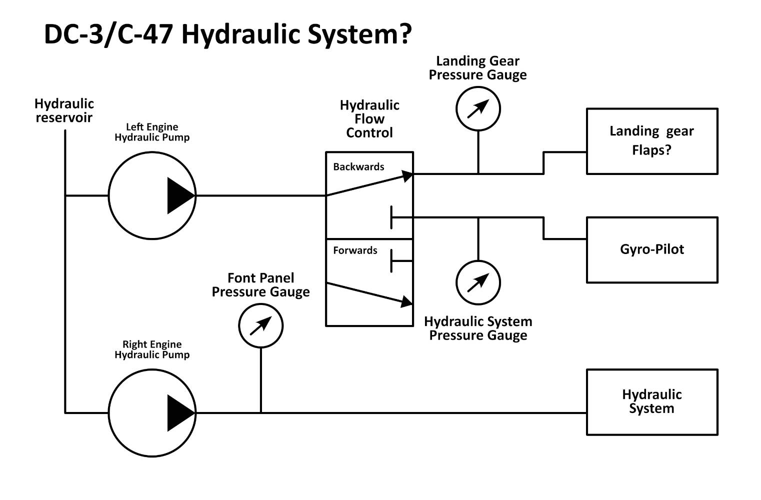
It has been suggested to me that this may be the correct arrangement. With the Hydraulic System and Front Panel pressure gauges have swapped what they are measuring.
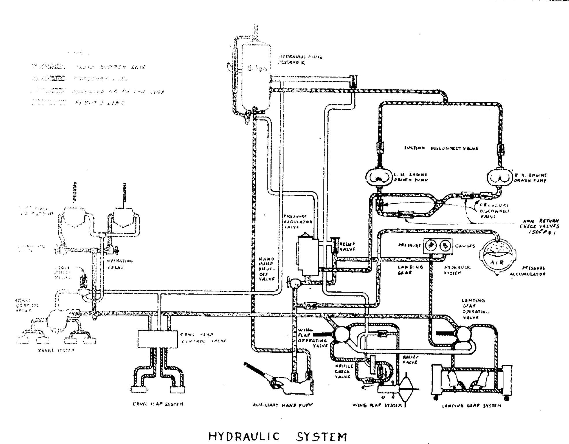
In an actual aircraft the hydraulic system is pressurized by both engines via common line to the pressure regulator. Pressure is maintained by the regulator at 600-875 PSI.
It is designed this way for redundancy should one engine’s pump be non-op.
The hand pump is able to pressurize the entire system if both engine pumps are non-op and/or if pressure is too low.
Again, in a real aircraft the main hydraulic pressure gauge is indicating the pressure for the entire system.
The landing gear pressure gauge is connected to the “down” line of the landing gear indicating pressure in the landing gear system.
The system is there to provide hydraulic pressure for the flaps, landing gear, brakes, cowl flaps, wipers, and gyropilot.
I just about never, ever fly the sim’s DC-3, so I can’t recall how it behaves.
The two ganged gauges by the copilot “should” be the main hydraulic system pressure gauge along with the landing gear pressure gauge.
It would make sense if the forward instrument panel hydraulic pressure gauge indicated pressure only when the blue engine hydraulic lever was placed in the gyropilot position, as that lever is severing the left engine’s hydraulic pump from the common feed of the main system to provide pressure solely for the gyropilot, and one would want to be able to monitor the pressure provided to that system.
As I said, though, I can’t recall how the gauges behave in the sim version of the airplane.
The diagram I provided is of a DC-3 without the hydraulic feed for a gyropilot. I’d expect a separate pressure regulator, check valves, pressure release valve, etc. for that entirely separate system driving the gyropilot.
The hard to read section on the left of the diagram is the wipers and brakes.
The thing with Aeroplane Heaven is they seem to take some pretty creative license when it comes to modeling aircraft systems and they are often pretty off-base.
I fired up the DC-3 in 2024 and it looks like the instrument panel Hydraulic Pressure gauge is, essentially, performing the same function as that of the Hydraulic Pressure gauge on the right-hand twin-gauge set.
There is no change in either gauge when the blue lever is repositioned.
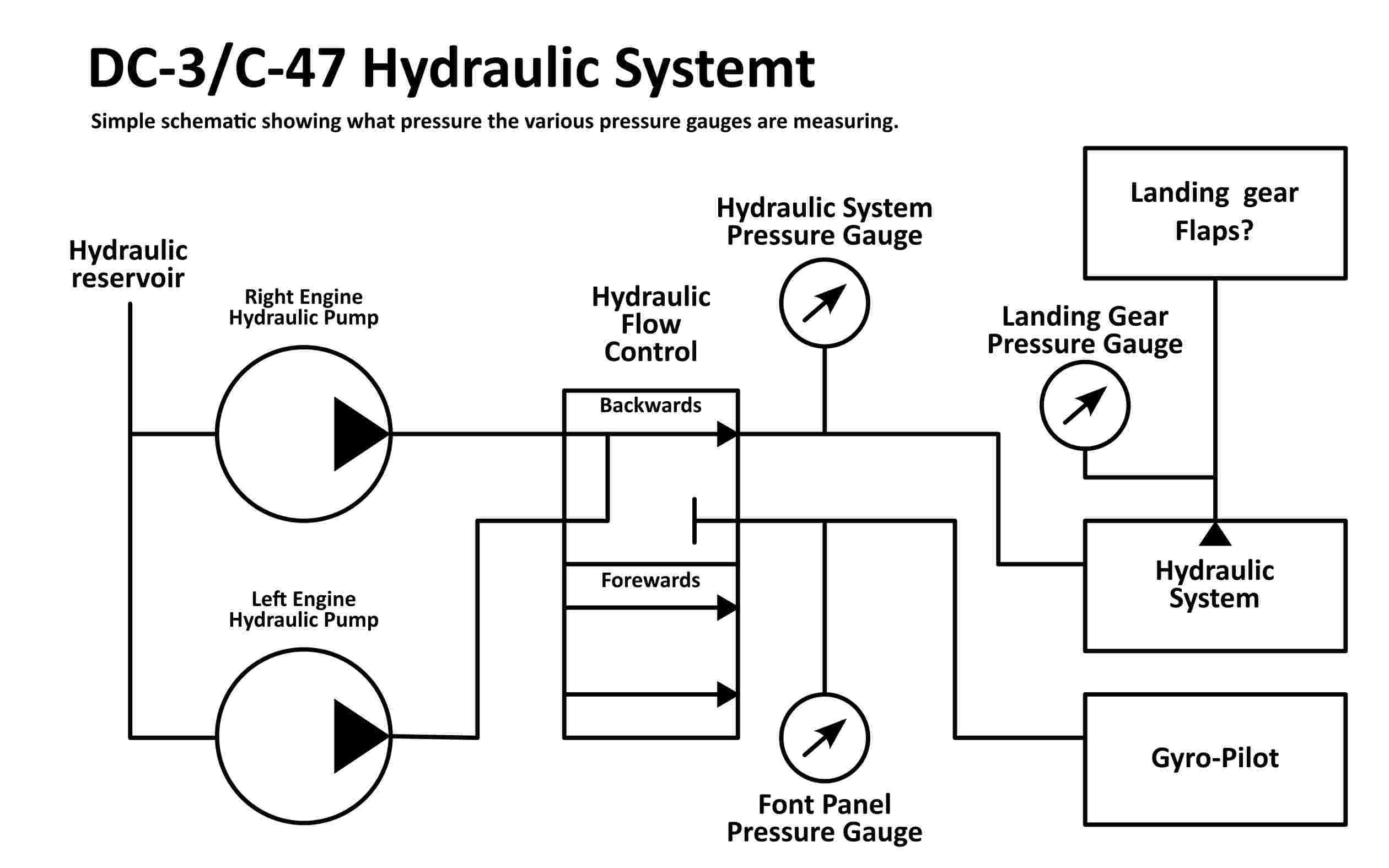
I’ll provide the solution for my own question but a big thanks the @NixonRedgrave and Imenes @Duckworks discord server. After various discussion and peering at the hydraulic schematic in the C-47 Training Manual and a bad photocopy of a DC-3 without Gyro-Pilot. So this is what I think the schematic should be to show what the hydraulic pressure gauges are measuring: