With the recent shortages of devices on the market, I decided to make my own for adjusting the trim. I want to put this in an enclosure and attach a wheel. I used an Arduino Uno and used the COM port. Then used C/C++ to read the values and pass those to flight sim 2020
Hi
Well done.
I’ve set up an arduino with switches and pots to handle things such as trim, gear, flaps, spoilers etc however the axis’s are all over the place - very jittery. I’d be interested to see how you got the encoder working. Care to share?
Thanks
PaulyFSPauly
Sure thing, I will get back with you in the morning as it’s 3am.here and I need to get some sleeps. But for the most part, I did a really “dirty” Job with handling inputs from the COM port of the Arduino Uno and pass those inputs to SimConnect for it to register in FS2020.
Eventually I will clean it up but for now it’s a little messy.
Haha
Don’t worry about untidy code… Some of mine is no doubt way worse!
It’ll be kind of you to share. I’m very interested because once you get one going, you can get 20 going! :rofl
PaulyFSPauly
The Arduino Uno doesn’t show up as a gamepad because of the architecture. The Uno was the only thing I had on had at the time so I decided to make something with that. I did just get a Arduino Pro Micro today, so after I solder the pins on, I will probably change my course and go that route.
I haven’t forgotten about you, the Arduino site is down which holds my sketchpads (Probably should store them locally). Once it is back up, I will post the arduino code for the encoder.
Hi guys,
I feel a bit of a cheat as I got the design and code form this YouTube video Button box video
I did do some modification to the code as I used an Arduino Micro and I also had two toggle switches that I wanted to send pulses on change. I also added diodes to my button matrix.
I am looking to add an external throttle quadrant and patch them in as 4 axises, but of course I have originally soldered my buttons to all the analogue pins
// Robust Rotary encoder reading
//
// Copyright John Main - best-microcontroller-projects.com
//
#define CLK 7
#define DATA 6
#define BUTTON 5
#include <Joystick.h>
Joystick_ Joystick(JOYSTICK_DEFAULT_REPORT_ID,JOYSTICK_TYPE_JOYSTICK,
  0, 0,                  // Button Count, Hat Switch Count
  false, false, false,     // X and Y, but no Z Axis
  false, false, false,   // No Rx, Ry, or Rz
  false, true,          // No rudder or throttle
  false, false, false);  // No accelerator, brake, or steering
int pin13;
const int16_t MAX_VALUE = 1023;
const int16_t MIN_VALUE = 0;
static uint8_t prevNextCode = 0;
static uint16_t store=0;
int16_t counter = 0;

void setup() {
  pinMode(CLK, INPUT);
  pinMode(CLK, INPUT_PULLUP);
  pinMode(DATA, INPUT);
  pinMode(DATA, INPUT_PULLUP);

  Joystick.setThrottleRange(MIN_VALUE, MAX_VALUE);
  Joystick.begin();

  //pinMode(LED, OUTPUT);


}


void loop() {
static int8_t c,val;
  //digitalWrite(LED, HIGH);


   if( val=read_rotary() ) {
  c +=val;

  if ( prevNextCode==0x0b) {

     counter++;
     if(counter > MAX_VALUE){
      counter = MAX_VALUE;
     }
     Joystick.setThrottle(counter);
  }

  if ( prevNextCode==0x07) {
     counter--;
     if(counter < MIN_VALUE){
      counter = MIN_VALUE;
     }
     Joystick.setThrottle(counter);
  }

   }
}

// A vald CW or  CCW move returns 1, invalid returns 0.
int8_t read_rotary() {
  static int8_t rot_enc_table[] = {0,1,1,0,1,0,0,1,1,0,0,1,0,1,1,0};

  prevNextCode <<= 2;
  if (digitalRead(DATA)) prevNextCode |= 0x02;
  if (digitalRead(CLK)) prevNextCode |= 0x01;
  prevNextCode &= 0x0f;

   // If valid then store as 16 bit data.
   if  (rot_enc_table[prevNextCode] ) {
  store <<= 4;
  store |= prevNextCode;
  //if (store==0xd42b) return 1;
  //if (store==0xe817) return -1;
  if ((store&0xff)==0x2b) return -1;
  if ((store&0xff)==0x17) return 1;
   }
   return 0;
}
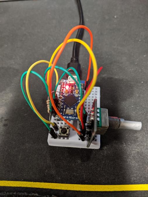
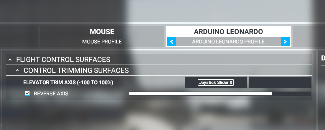
Here is what I ended up using on the Arduino side. I just got my Micro and switched so windows can register it as a game pad. From there, Flight Sim recognized it and was able to set the trim to the joystick throttle.
ya sure, so I got an Pro Micro board which registers as a GamePad in windows when connected via USB. Link below. This will be recognized as an Arduino Leonardo in windows. You are able to use the Arduino IDE and it will be recognized as a arduino controller. I used the following library to create the joystick setup. I set the encoder to be recognized as a Joystick Throttle.
From here I was able to get WIndows, and MSFS2020 to see the controller and could bind it in game. Before I was using an Arduino Uno which isn’t seen by Windows as a game pad, thus it’s I switched it up. This allowed me to not have to use SimConnect anymore.
Can I ask why you’ve gone down the route of creating a virtual axis rather than up down buttons?
I’m using one of the encoders on my button box as button presses. I am thinking of adding some sort of ballistic algorithm, as there are times when trimming that you need to turn the encoder quite a lot.
With the axis, I can set the min and Max values of the axis on the Arduino side. That means I can easily tweek how much I want the axis to move by a single turn. If you see the button on the bread board, that is a multiplier for the max axis value, by just clicking that button, I double the length of the axis, and can make my trim dialing even more precise. I’m going to eventually going to make another knob that will lit you easily change the sensitivity of the encoder so the user can set it to how they would like. With the axis, you can get way more precision out of it than just assigning up and down values.
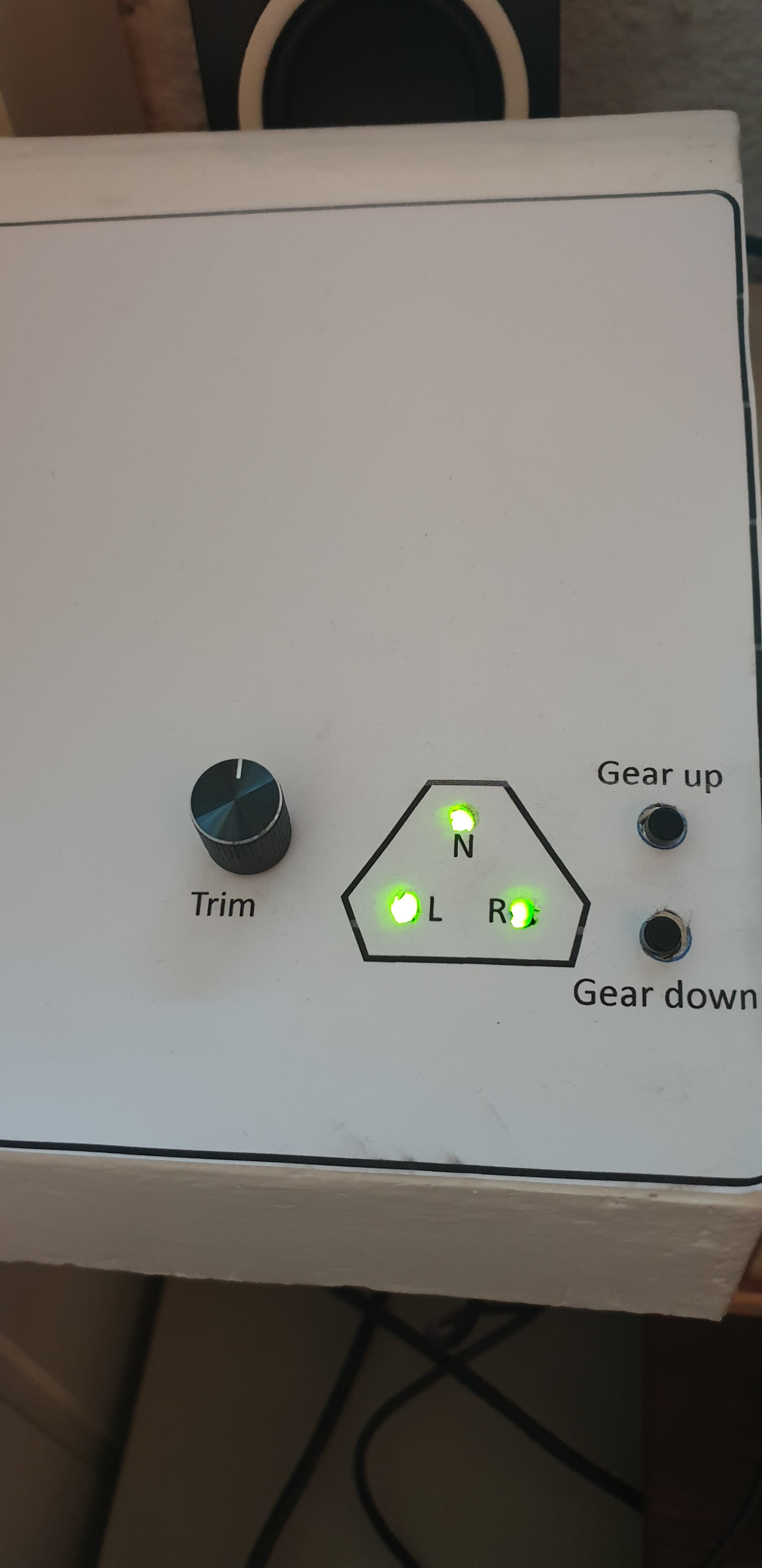
I have made a similar setup. One potmeter as a second youstick Y-axis for trim, and two buttons for gear up and down.
Currently using an Arduino Leonardo for this. (Also used an UNO, but this needs to be flashed to be able to work as a joystick)
But I would love to be able to also make MSFS “write back”.
Not sure if that is possible when using the arduino as a Joystick, but should be possible using other methods.
Unfortunately I have not been able to find anything for neither UNO nor Leonardo..
Mentioned this in another thread:
OK. Here is some explanation to my current setup:
I have one setup where I use a Arduino Leonardo that simulates a Joystick.
Here I have 1 trim rotor, two buttons for Gear up/down and three lights.
Here is the code using the Joystick-library mentioned above.
Just upload and assign keys inside MSFS:
#include <Joystick.h>
Joystick_ Joystick;
int gearDown = 1;
int countMax = 100;
int count = countMax;
// Constant that maps the phyical pin to the joystick button.
const int pinToButtonMap = 3;
// Last state of the button
int lastButtonState[10] = {0,0,0,0,0,0,0,0,0,0};
void setupPins(void){
// Set all the digital pins as inputs
// with the pull-up enabled, except for the
// two serial line pins
for (int i = 2; i <= 12; i++){
pinMode(i, INPUT_PULLUP);
}
pinMode(A5, OUTPUT);
digitalWrite(A5, gearDown);
}
void loop() {
// Read pin values
for (int index = 0; index < 10; index++)
{
int currentButtonState = 0;
if(index < 2){
currentButtonState = digitalRead(index + pinToButtonMap);
}else{
currentButtonState = !digitalRead(index + pinToButtonMap);
}
if (currentButtonState != lastButtonState[index])
{
Joystick.setButton(index, currentButtonState);
lastButtonState[index] = currentButtonState;
}
}
Joystick.setYAxis(analogRead(A0));
Joystick.setXAxis(analogRead(A1));
Then on the Arduino side I have the following code running:
if (Serial.available() > 0) {
  byte incomingByte = 0;

  incomingByte = Serial.read(); // read the incoming byte:
    heading = incomingByte;
    lcd.setCursor(0, 0); // set cursor to first row
    lcd.print("Heading: "); // print out to LCD
    if(incomingByte == 35){
      cursor = 0;
    }else{
      lcd.setCursor(cursor, 1); // set cursor to secon row
      lcd.print((char)incomingByte); // print out the retrieved value to the second row
      cursor++;
    }
}
There is definately some room for improvements, as I now send the # for recognizing when the text stops…
But so far working fine at least