. Part 1/2")
Hey… thats me… I need to check this forum more often. Thanks for the mention. Hope you have many safe flights!
Hi Bits and droids / @ffsDaveffs
I’ve enjoyed your videos, and thanks for publishing all the code and connector. I’m trying out the library and the simple throttle worked ok. I’m trying a more advanced panel now (converting from a ‘Link2fs’ setup I had). I’m starting with the basics - a few push buttons to turn autopilot on and off but currently it’s not working and I’m struggling to debug. I’m using an Arduino Nano, which is basically a smaller form factor Uno with serial port and ATMEGA328P MCU.
A few observations:
- The ‘status’ message could be a little more verbose. E.g. a status light or message for each of:
– connected to simulator/game
– connected to arduino to send controls (with option to enable debug messages, like a serial monitor, while running)
– connected to arduino to receive variables
Currently the ‘successfully connected to your arduino’ comes up, but it’s sticky, even when you stop the connection it’s still saying connected. Also even connecting to any com port, e.g. com1 on my PC which is empty, seems to say successful. i.e. there doesn’t seem to be a test to check it’s really talking to an Arduino with the BitsAndDroidsFlightConnector library running.
[Updated]
I’ve also managed to get the “lcdComUnoMega” example working. The comment at the top was key:
//DONT FORGET TO ADD A 10Uf capacitor after installing the sketch between ground and the reset pin on the board
Not sure why this was required, but without it, it seems every bit of data sent to the arduino triggers a reset? It would be good to add a note about this on the main library documentation page.
So in summary - the simple analog throttle works, the simple comms to LCD example works and I’ve modified this to show avionics data.
What’s not working for me yet is sending push button input data to the simulator. Looking at the TX led on the nano, there’s no flashing when I push buttons, and nothing in the serial monitor either.
Any pointers on how to debug further would be welcome ![]() Thanks again for sharing the connector, libraries and videos. It’s a lot of work.
Thanks again for sharing the connector, libraries and videos. It’s a lot of work.
Regards.
Neil.
You are absolutely right. The status messages are a bit off currently and seem to stick after a successful connection. I’m working on a fix but found out too late for this to be implemented in the update releasing tomorrow. But in the next one, it will be fixed.
The 10Uf capacitor will be more prominent in the docs (it will save me some support mails as well I hope).
Currently, there is a bug that keeps the line hostage if you use it as an input. so currently it uses 1 comm port for either in OR output. I’m working on a stable fix. When used as an output a button command can be sent by using Serial.println(connector.sendApMasterOn()); Which in the backend just translates to Serial.println(301); This should work combined with the throttle (unless there is an insane amount of jitter from the potentiometer on the line blocking all the communications (which in reality shouldn’t be the case)) but it won’t work in combination with the retrieving of data (that is being worked on). In the upcoming update, I fitted an algorithm to handle jitter though. As a workaround, I currently use an Arduino for inputs and an Arduino for outputs or a Teensy with 2 comm ports.
So all in all thanks for the feedback I’ll get right on it!
Hi Bits and droids / ddsDaveffs -
Thanks for your reply, and I can see your latest releases are getting stronger all the time. The documentation is clearer about the 10uF capacitor, included examples, and the status messages in the connector really help with debug. I managed to debug my issue and get it working just fine. Thank you!
I can see you’re putting a lot of hours into adding extra features and videos, thank you for sharing all this!
For me there is just one feature missing that I woudl love to see in a future release – bi-direcitonal input and output from the same arduino (at least it was missing last time I checked).
Here’s my use case:
Light up- LED buttons that work as inputs, but also show current simulator state as well as LCD panels that allow a single rotary encoder to cycle through different functions, e.g. altitude & virtical speed.
Example: Autopilot
Previously with FSX and the Link2FS connector I built a simplified replica KAP140 autopilot which has buttons that light up when active (e.g. AP, HDG, NAV) and an LED panel that shows current mode and target altitude and vertical speed:
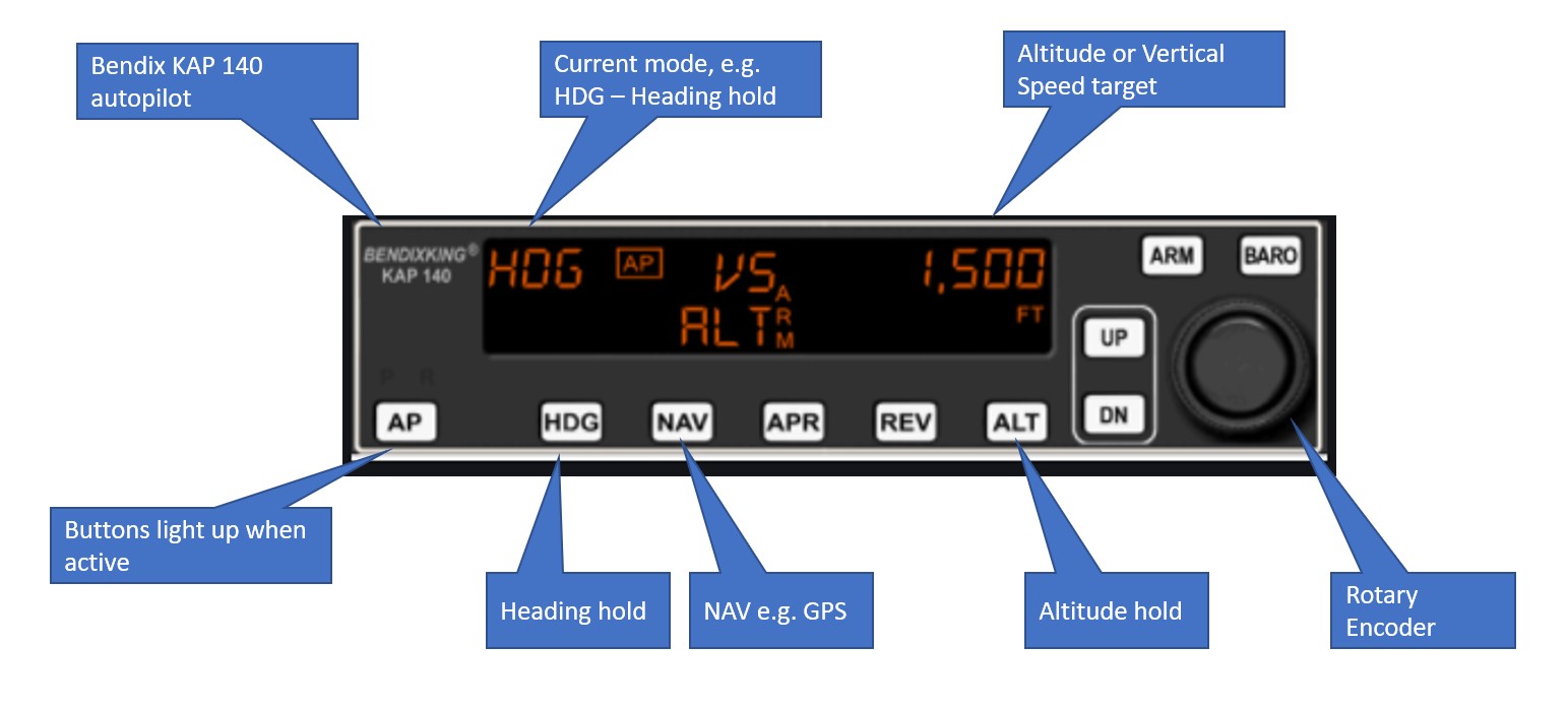
I have built a working replica some years back with the Link2FS utility, however that does not support MSFS 2020. I’m really keen to move this over to Bits and Droids as your library looks much easier to use!
The picture below shows a flow chart of what I’m aiming to build (this is replicating what was working with Link2FS). Basically received variables sent to LED button lights and the LCD panel; inputs processed from buttons and rotary encoder. When pushing the rotary encoder click I can cycle through Heading, Alt and VS settings (the underline on the LCD cursor moves as appropriate).
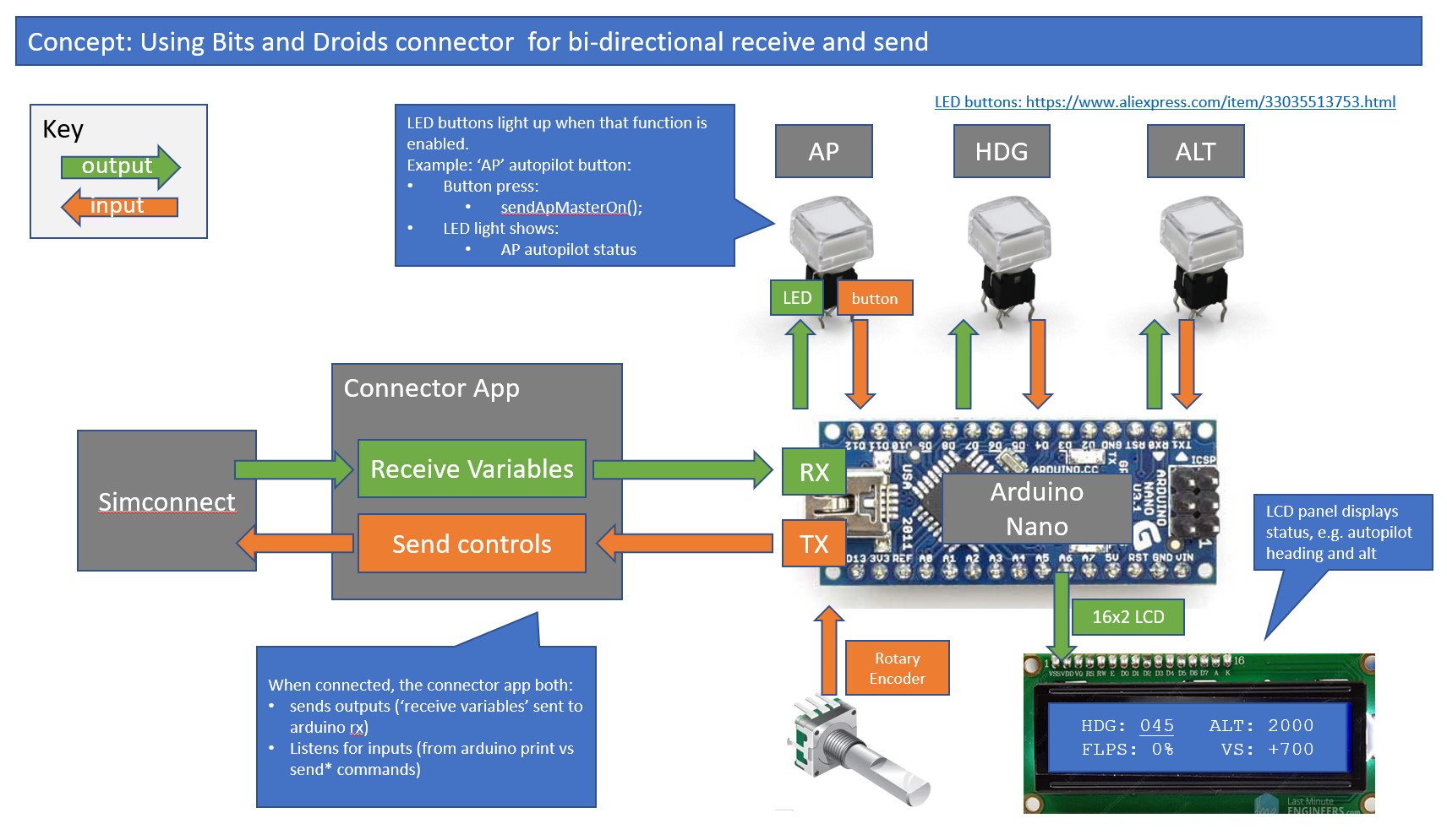
I can imagine getting both RX and TX working with the same Arduino needs some careful attention on the connector and library sides but it could open up some very interactive and dynamic interfaces, e.g. sharing a rotary encoder with different input functions.
Reference - Link2FS
If youv’e not seen it, I’d recommend taking a look at Link2FS as it’s covering many similar functions to yoru connector. You can many simularities:
- Multiple arduinos connected – in this case they call them ‘cards’
- SimConnect Extractions == same as your Receive Variables
- SimConnect Inputs == same as your send controls, they use a letter and number combination, e.g. C02
- note - once a device is connected, it stays connected until the disconnect button is pressed. No need for the 10uF capacitor as it doesn’t connnect/disconnect/reset with every message.
Here’s a video that may be interesting to you ![]()
Youtube video - Link2FS example
Many thanks for your continued development, and hoping you can consider bi-directional comms in a future release.
Neil.
Good afternoon OneSeventyTwo, Thanks for the very elaborate response. The Bi-directional coms have been in the works for quite some time. I managed to get it to work on values that change on a rather small interval(like you mentioned the toggling of a button and lightning an led for example). Issues started to arise when I started to combine it with data that changes rapidly (i.e. airspeed, throttle values, etc.). I’m currently still figuring out whether I need to limit the choices of in/outputs when using bi-directional communications or find a way to make it work no matter the choice. It is in the works but it needs a little bit more time to come up with a solid solution. I know in the current state my inbox would get flooded with bug reports with many edge cases.
Hi @ffsDaveffs,
Seeing cheap price of Nano, for some like CH340, could it be right to consider using a two boards solution, one dedicated to INPUT and the other to OUTPUT, in order to get a workaround in the bottleneck issue ?
That is correct I’ve been running with about 3 arduinos going in and 1 going out as a temporary workaround (the 3 in are pure laziness where I didn’t want to combine separate physical modules)