Yes, I linked that page one or two posts above. If you read, they have a custom controller and custom electronics, it’s not a HID device.
No its a self written program that I held quite generic. To be more precise it is a SDK Sample I modified. The sad thing is that partially even the MSFS SDK Examples are not working correctly / at all. 
As I understood, third Party programs like FSUIPC and Mobiflight both use Simconnect. So I wanted to avoid those and directly connect to MSFS through Simconnect to not be reliant on these Frameworks.
So far, I just got the Joystick and Throttle Axis working. For now all Variables I pointed out in the link above, can be used.
Everything is still a work in progress. I am currently on a work trip so I cant access my personal files Right now, otherwise I would have sent you my source files.
Otherwise you can install the MSFS SDK and have a look into the SimVarWatcher example.
I will now proceed and start designing the Hardware Part for the FFB / Yoke Controller… At least thats something I know how to work with.
Did you already give a thought on how to implement these or which motors to use?
I see. Yes, those were the programs. I was asking to know what protocol mobiflight uses on the serial port but no one was willing to describe it… so, you did well. I wish I were able to program on PC and do the same that you are doing. Which language did you use?
Not yet. My biggest concern was/is the USB part, I’m not to worried about the motors. I still need to think about the mechanics too, I would like to avoid to blindly copy something else, but from what I have seen there aren’t many variations on that side.
I was reading that people suggest to use brushless for FFB application for both performances and durability. I need to understand this better, because as far as I know, if a (sensorless) brushless loses the synch with the phases, it behaves like an unsychronized stepper, so it loses any torque. And here motors are not going to be spinning much, they are just going to pull back and forth. I remember when I used some brushless motors that, if I was accelerating too quickly, they would just stop and start vibrating.
I know commercial, cheap FFB joystick use normal DC motors, but I don’t know what they use on higher level products.
But to start developing, I would really recommend the solution I have adopted. Motorized potentiometers can represent quite well your FFB system, you just miss the toque, but the response is there.
The biggest issue is not enough force. This guy modified teh FFB2 by doubling up teh motors:
I looked at micro hydraulics and pneumatic stuff at one stage but the ideal solution to get serious force would possibly be linear actuators. In the end I just bought a fulcrum non FFB yoke instead.

Yes, this is why for me a joystick electronics was a no-go.
Linear actuators have an issue, as far as I know: once they are moved, you can’t push them back due to the mechanical structure (gears, …what’s the name in English… worm… something?
This thing here:
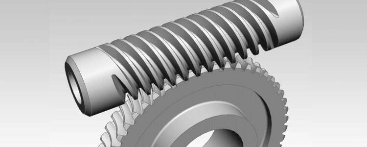
transmits movement only in one direction, from the motor to the linear part, not the other way around. Or am I wrong?
If that is the case, they are not usable for a FFB device that has just to push/pull the controls, not lock them in one position.
But I do think that motors are sufficient, at the end, even on a plane with mechanical controls, it’s not that you need to apply 100kg to move a yoke…
Yeah you could not directly connect the linear actuator to the yoke shaft there would need to be some sort of spring/damper between them so basically the actuator was moving the natural point the yoke wanted to sit but you could force it away from that position.
Ah yes, I had that idea at the beginning too. But on one side implementing friction and effects based on movement would be really difficult, on the other side high frequency effects would be limited a lot.
And also the only effects based on spring/dampers are… sping and damper It would be really difficult to implement a 100Hz sawtooth force with all that mechanics in the middle.
I used C# for that which is (as I understood) the preferred language for the SDK.
When I get home I can upload my Code to Github. If you do all the math in the Controller it should be pretty straight forward to send out the Values over HID (thats what I am saying now. ![]() ).
).
Hmm… as gpaolo said I dont think this will work due to the worm gear used. Normally you would use the positional Feedback from the Stick Position to adjust the deflection and power on the motor. I think gpaolo is more into this topic so he could explain this a little better ![]()
Yeah… But these are really tricky to control (if you want to do it yourself). You would basically then have to monitor the slip in regards to the commutation frequency. The advantage is that you can run them very precisesly as your controller does the commutation itself. This means you can already have the full torque at 0 rpm without any force stopping the motor by increasing the winding current without commutating the phases.
The DC Motor on the other side only has a Voltage input. Meaning more voltage → higher torque and more rpm (when no load is applied). This means you would have to increase the Voltage when you want to create a load but it is only possible when something (your hand) applies a force in the opposite direction. If you dont regulate fast enough and remove the voltage when, lets say your hands slips from the yoke, the external force is removed you end up spinning your yoke around like a steering wheel ![]()
Having DC Motors for the Flight Yokes is not as big of a problem as for steering wheels, since the movement is smaller, nonetheless I would go for the BLDC solution with an Outrunner/Servo motor.
Where I am not sure yet is I would go with a industrial solution or a DIY controller. As I saw the common wattage for such motors in Racingwheels is around 750W… which I would consider quite a lot for a small PCB.
I wasnt sure if this would be applicable for the Flight Sim Area so I looked up the Forces a plane comes up with. According to an agreement of the Navy I found while googling, the maximum stick force should be around 30-35 lbs.
Lets assume the Stick and Yoke Force are the same (I dont know ![]() ). My Yoke has a diameter of around 220mm. With the 13,5 kg (converted from the lbs above) this results in a torque of 14,5Nm.
). My Yoke has a diameter of around 220mm. With the 13,5 kg (converted from the lbs above) this results in a torque of 14,5Nm.
This means when using such a motor you could implement a 10:1 reduction (Pulley) to reach the maximum allowed force… Which I would probably crack your table nad yoke. ![]()
Ah, C#… I started studying it, then I had to give up due to lack of time ![]()
I’m fine with C, but my last experience on PC programming was Visual Basic… 2? 3? Never done object stuff. Still have problems to see the difference between an object and a function ![]() I mean, I grow up between basic and goto, you can’t pretend too much too quickly
I mean, I grow up between basic and goto, you can’t pretend too much too quickly ![]()
![]()
It is correct.
There are effects that apply a “blind” force, like constant force or periodic forces, independently from what you are doing with the controls, but there are others that uses position, speed and acceleration to calculate the force to apply, so they are calculated dynamically.
But, in my view, the biggest obstacle is that to apply linear forces, when you have a spring in the system, you need to… linearize the response of the mechanics by compensating with the motors. That’s not easy at all.
Yes… but then I wonder, if you do have a rotation imposed from outside, the moment the motor moves you lose the torque. I really have no direct experience of this application, so I would need to try it before going for it.
My idea would be to control in current, not in voltage. So you actually set directly the torque.
With a DC motor that would be easy.
Without worrying too much of efficiency: get a voltage from the PWM, use it as a reference in a current sink, apply it to the motor with a H bridge. Only limitation might be dynamics due to the need to filter the PWM, but it should be possible to get a fairly clean reference from a high frequency PWM, keeping around 500Hz bandwidth.
But the point is that if you apply 1A to the motor, that will provide that torque whatever the speed it. If the motor is stuck because you are holding the controls, it will still apply that torque even at 0RPM with a very low voltage. Keep in mind that the motors here will do just a few turns from one end to the other, so 0RPM is almost the normal working condition.
I would go for custom design if I do the current driver. Hell, I’m an electronic engineer, if I don’t go for custom design for motor driver I’ve got the wrong job ![]()
Definitely ![]() and your arm too if you are not careful
and your arm too if you are not careful ![]()
But that is the reason why I haven’t started the mechanical design yet. One of those DIY/conversion projects linked before, they went to a V2 because they were saying that 3D-printer parts are not strong enough for the forces that needs to generate the yoke.
So mechanical design won’t be trivial.
Also because… I was thinking, when I’m hitting one of the end of the movement, I can’t put a limit switch and power off the motor, I need to keep it running, otherwise you will get a lot of hammering when you try to move it and the motor restarts. So, basically, the structure must be capable of resisting the max torque indefinitely with a mechanical stop.
Now, add this to my philosophy of 100% margin… the whole structure will have to be quite resistant.
I need to ask to one of my mechanical engineer colleague… although I never got anything close to a design from him, I need to try ![]()
As a sidenote (dont know if you know it already) there is the OpenFFBoard that looks quite promising. The controller Firmware as well as GUI seems to be open Source. I just watched the last two videos on his youtube channel where he also has some links in the description to his github account.
The small FETs on his Driver Board seem… impressive.
What is impressive is the size of that motor  did you see how the bench flexes while he’s driving?
I think @tsaG13374551 was quite right, it’s going to crack the table.
I actually wonder how they deal with the end of the movement, the wheel can make more than one turn, so it can’t be a mechanical stop.
In this respect, a yoke is quite simpler.
I think I did look at that code when I started this project back in December, the name sounds familiar. I’ll have a second look.
Right now I need to finish to implement the last effects and I want to go back to try to understand why everything stops working when I add a serial port to the HID. Seeing those housekeeping from the wheel and not being able to do the same is quite outrageous 
Why not put a pair of load sensors in the yolk handle. Make it a differential pressure feedback system. That way your not guessing at, of having to calculate, the applied force.


I was thinking more along the lines of the add in load sensors people use in their brake pedals. Use 2 load cells and a position sensor for each axis. Software says go to a given position and use this amount of force to hold it there. Force would increase on a curve as the user deflects the axis away from the intended position. The load cells could also serve as the end stop switches.
No worries about breaking the table or your arms.
EDIT: I remember reading where someone used the load cells from a bathroom scale for their brake pedal mod. 4 cells that can handle 300 lb of load total ( 75 lb each) for about 30 bucks. The question is , would this be easier to program for? I’m more a mechatronics design than software kinda guy.
I know, a “software kinda guy” would be useful to me too
I can’t really understand the setup you are describing, maybe we are talking about two different things? Because I’m thinking about the yoke but you mention the pedals…
Anyway, that gave me an idea. If I put touch sensors on the yoke, I can reduce -for example- to 1/10 the torque when no one is touching it. In this way, it won’t bang against the mechanical ends: it will still move, but not too hard.
So, yesterday I have finished the effects, but I need to re-implement damping and inertia. At the beginning I made a very simple, dirty implementation of speed and acceleration (delta-t is given by the 500Hz timer that updates the effects, so I do V=position[now]-position[previous] and A=V[now]-V[previous], which is formally correct but in practice it doesn’t work. So I need to see why and how to make it right.
I have optimized the code moving many calculation from the interrupt routine (it was a pain just to see them there, although the microcontroller seemed not to care at all… that thing is unbelievably fast) to the reception of the data, so now many of the parameters are calculated when the effect is requested. There are a few more … polishing that can be done, but that would start to impact (my) readability of the code, so I’ll leave them for now.
I think I’ll move to my second attempt of getting the serial port working on the USB, I really want to see data.
I only mentioned the pedals as a reference for s low cost sensor solution.
I will draw up my idea for the incorporation of load sensors this evening using the V2 as a reference design.
Yes, there is no mechanical endstop here. They do have an implementation that will increase the force at a certain point. Basically a electric Endstop by Increasing the Force up to maximum so you are not able to turn further. Kind of shown when he explains the dead band or in his latest video at 0:30.
You could also monitor the current which is more or less directly connected to the Force at a constant Voltage but (I think) this only works with a Brushed motor.
It looks like there is more to this OpenFF than the YouTube channel. The Discord seems quite active. I think I will modify my Cirrus to this controller and then add the OpenFF Firmware/Motor Module (don’t want to solder those Chips with GND Heatpad. ![]()
As a proof of concept, this is my haptic experiment by using a BLDC motor with a shaft position encoder feedback. The haptic controller is made with STM32 Nucleo board connected to the PC with USB in HID mode. USB data send the user input from Nucleo board to the simulator, and the simulator variables and parameters to the board in the other direction. There is an additional piece of software written in C++, using SimmConnect protocol, interfacing between USB interface and the simulator.
The controller can use various modes of a haptic device, like the spring mode for joystick axes, free lever with a single detent for throttle lever and multi-detent lever for flaps and gear levers.
This is an example of a flaps lever. The user input changes the flaps handle position in the simulator:
By changing flaps position in the simulator (mouse action) the physical lever is adjusted accordingly:
I have managed to get the UART together with the HID 
What a pain…
I’ll reply to the last posts tomorrow, for today, I’m done 
In the free time from the free time work ![]() I’m reading about brushless control. I’m a bit worried because my searches give me as result mostly academic papers and no real circuits, so I’m starting to think that torque control on brushless isn’t trivial at all.
I’m reading about brushless control. I’m a bit worried because my searches give me as result mostly academic papers and no real circuits, so I’m starting to think that torque control on brushless isn’t trivial at all.
Also, everyone normally considers that the motor is spinning, while in this application the motor is almost always static. I found only one page or two describing this situation, but again, all theory and no circuit.
I have the feeling I’ll never know until I try.
But now that I have the serial port running, I can start doing two things.
One is receiving all the data calculated by the code, so I can finally see what’s going on inside the micro. The other is that I can control the effects through any protocol I can make up, even the same that you use in your interface.
So, now that the UART works, my next step is building some housekeeping functions, and then try to sort out speed and acceleration calculation.