Force Feedback Yoke project

Hi all,
I have started some time ago my idea of building a force feedback yoke, or generally speaking, a force feedback device.
I have studied some documentation, which is unbelievably poor and difficult to find, and start looking at some examples, as I never worked with USB -and I can’t say I missed anything.
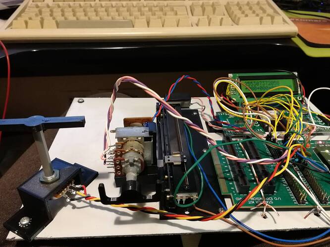
So I came out with a test platform, someone might remember from another discussion where I participated, I don’t use AVR and all the Arduino stuff, but I work with PIC. So I got a demo board for one of the PIC with USB support, a couple of demo board for motor drivers, an LCD to get some debugging information (when you stop the program, the PC disconnects the USB and everything stops…), and then I had the idea to use two motorized potentiometers to simulate the yoke, as I needed something real to see the effect of the movement and implement all the effects.
I have made a couple of simple video a few days ago where I was testing the constant force effect, you can see them here

I made some progress since then and now also spring, friction and damping are working.
I am still working on the periodic waveform effects, but I wanted to give it a try with MSFS and XPForce… and it worked well!

The reason why I’m writing now is that I’m a bit stuck and maybe someone can give me some indication.
The tool I’m using to generate the effect, called ForceTest, is very limited and it is missing a number of effects. I could not find anything else online, and even this one was difficult to find. Since from the documentation of USB.org is impossible to understand what really arrives to the other end of the USB cable and how the different effects are specified (I have just discovered by sniffing the USB packets that the effect “grooves” is just the effect “sine” with some fixed parameters, for example, but it’s not written anywhere…), I need to have something on the PC that I can use to send the request of the effects and see what I’m getting.
Is anyone aware of a tool of this kind?

Just for curiosity, it’s still very much work in progress and at the moment I’m more focused on the USB implementation, but I have modified the descriptor to have 16 bit resolution on axis, I plan to include also a number of buttons and switches for any use, and I’m thinking also to add a separated module for the throttle control. But before that I need to get the USB part done and also put together some prototype for the mechanics.
I have been reading that people normally suggests brushless motors for force feedback design, but I’m a bit reluctant. Torque control on normal DC motor is fairly easy while on brushless is more complicated, and also I’m not sure if a brushless that can’t move as it’s commanded will lose the synchronization with the phases like a stepper motor and lose torque. I don’t know, I need to investigate more on that anyway.
But if this works, the project can easily be adapted to yokes, sticks or any type of control, possibly even dual commands. That would be interesting, actually.

Well, I hope someone can give me some hint about this testing program I need, that is the most urgent part. I’ll see if I can make some new short video of the other effects.

7 Likes

Hi gpaolo,

this looks awesome! I am also currently looking into this topic as I want to implement FF to my Cirrus II Controller. I struggled as well to find a decent documentation on this topic. The main area, where FF is currently used is the Racing Sim. I already created my own Little controller board for it to convert it from serial to USB HID controller which works great but lacks the Force Feedback. Mechanically, the yoke allows to be modified to FFB easily. However, what I’m struggling with is the software support. I that XPForce can be used for this purpose which allows the support of directinput controllers.

I found the MMOS controller at virtualracing.org but it looks like it only supports one axis.

I am mostly working in the Arduino Area as this is where I am most familiar with. A big plus is also the huge community. Which kind of Devkit / Chip are you using?

My next step would be to look into the XPforce area, to see if I can find any examples how the devices would be handled.

Hi,
indeed, I could find only steering wheel stuff!!! Quite frustrating…
I use Microchip PIC, I have all the development tools (debugger, programmer… experience :smiley: ) for those devices. Community for PIC is quite big too, not as big as the one for Arduino, but mostly because majority of people using Arduino knows very little of low level programming or electronics in general, so they are more than the ones using PIC :laughing: jokes aside, PICs are less… commercial. I did use AVR in the past but I didn’t like them at all, PICs were a lot better as devices and I kept going in that direction. AVR were a lot less popular than PIC until the Arduino came out and they made these development boards and libraries where people could forget that they were using a microcontroller and not a PC, IMHO taking away most of the meaning of using microcontrollers (highly optimized code, custom electronics, specific optimized design, etc.) in favour of making it popular. But let’s stay away from philosophy here :smiley:

I’m not using a “devkit” strictly speaking, I design my own electronics. In this case, as I had no previous experience with USB, I wanted to avoid a few… variables and I bought the USB Starter Kit with the expansion board, with a dsPIC33EP512MU810 running at 64MHz (internal clock) and all the peripherals I need to implement motor control and communications with hardware modules. And very fast mathematical operations too, I’m using quite freely sine and cosine functions to calculate the force vectors and I have no speed problems.
But once I’m confident that everything works I’ll design my own PCB and start working on all the analogue section, real motor driver, signal conditioning for analogue inputs, etc.

I can recommend you to start with ForceTest to begin the implementation of FFB.
I started from this code
https://www.microchip.com/forums/m958105.aspx
and you can find here all the conversations about the USB descriptor (I’m gpaolo on that forum, I can’t change my name on this one…).
This doc

is rather … abstract, but it gives you some idea on how to read the descriptor.

The point is that the joystick, or the device generally speaking, gets recognized by windows as a standard force feedback device, and then windows knows how to use it. There is some freedom in the definition (as I said, I can add axis and buttons, change resolution, etc.) but it has to be declared as one of the commercial devices with PID and VID, or you would need to create also the driver.
So, with my code, I’m using the PID/VID of a Logitech G920 -no particular reason, it was the only one that I managed to get recognized by win10 as FFB device- and XPForce didn’t ask me anything, just started to send the effects the moment the simulator started.

IN PROGRESS | VR FlightSim (wixsite.com)
Start with a MS FFB2 and go from there. seems pretty straight forward of a build.

Yes, agreed. Most people just want to get things done fast and copy code snippets. If no one has done their problem before, the run agains a wall (metaphorical :slight_smile: ).

I am more familiar in the electronics, PCB area. So UART was mainly all I needed and managed to evade the USB topic so far.

I didnt look into the FFB implementation of MSFS so far and was just thinking how it is done and if the USBHID implementation gives one such a big advantage that it is worth all the mess. If it needs a program in the middle anyway I would do the conversation from the FFB Data on the Computer and then shovel out everything over UART.

I hope within the next days, I have some more time to do some more investigations to catch up on this topic. :smiley: So far, what you did already looks awesome. And using already available standards like you did should always be the first way to go.(y)

Maybe a stupid idea and i do not know how to accomplish this but,
In earlier days on the soundcards they put a gameport 15 pin connector on the card
After that they came up with usb,
Later there was buttkicker and as far as i understand this worked through output of the soundcard, in my opinion there might be a way to combine this to one another. Partitially input by moving the stick as input and get feedback from rumble on the run/taxiway as output translate to the stick
Every airplane had ffb settings in cfg files also editable in microseconds for bumps etc.
I know this sounds messed up, but it is straight out of my head. And it seems to me there is a relation between the two from the beginning each follow-up there own way in devellopment.

Regards

Sebastiaan

Great projects folks ! Loved to read this topic.

1 Like

Yes, this is one of the websites and projects I have been studying before deciding to start my own design.
One reason, I could not find any FFB2 on ebay at a reasonable price. Second reson, I would be limited by what is already implemented and I could not add anything. One of the comments I have been reading is that you need to provide enough force, and while the drivers for a joystick might be sufficient for that application, a yoke might require a different one (for example, the torque you apply rotating the yoke just due to the size are different from the ones you apply on a joystick). If you see on that website —I think it was that one- they are working on a V2 because the mechanics is not strong enough.
And, as I just thought yesterday while I was writing one of these posts, I think it would be great to add a link for a second yoke to be able to share flight with another person.
If I knew how to do it, I would do the driver too: windows support to FFB devices seems to have been rather poor. Actually, the major issue that I still have to solve is that my device works on my Win10 desktop but it doesn’t on my Win10 laptop, where it gets recognized by windows as a non-FFB joystick. In the device manager everything looks the same, same drivers, same PID/VID, same descriptor… but windows doesn’t tell directX that FFB effects are available. I´ll go back to this once I am more advanced on the effect implementation.

Yesterday I have implemented the sine effect, it works fine. I need to adjust slightly the timers, as it is just a bit slower than the 500Hz I predicted, but it works fine.
I start to see that I need to add an input for the pedals, as I can´t control the plane on the ground just from the yoke.
I’ll try to make a video of the sine and grooves effect later. Still need to find a way to test the other waveforms, as I have no way to request them…

1 Like

same here. Love UART, it’s everything you need. Unfortunately PC likes USB… I had been using USB/UART converters, but on PIC side I always remained on UART. SPI causes me already some headache, I2C is already borderline :sweat_smile:

Well, as far as I understand, it’s simple. MSFS doesn’t support FFB. There are a couple of threads here too, also in the wishlist section. I think it’s a bit naive of them to have left this support behind (as well as the support of the VR controllers), to be honest.
You need to use an external program that, I imagine, reconstruct the type of effect that you need from the aircraft parameters transmitted by the simulator.

If, like me, you are completely ignorant of driver programming, the big advantage is that you can design something that looks like a standard device and you don’t need to worry about the implementation of the interface.

That could be one way, but at the end, your PC would still see a FFB joystick. So you would add one conversion step in the middle, but the work would be the same. Unless you know how to implement a XPForce-like program that sends directly the information out on a UART, in that case it would be a lot easier. But as I said, PC programming is totally unknown to me.

Thanks. There are still a number of thinks that I have not implemented, and I don’t know if I need to. Custom forces and forces report for example, it seems that they are not used by the flight simulator but I can’t understand if they are necessary for the general implementation.

That would work only for effects that are associated with a sound, but for example friction on the controls, spring effect to recenter them, etc., they don’t have any sound associated.

Hm, I just had a thought…
There is no FFB on the pedals, right? Because I haven’t seen any driver that supports a third axis for the forces, it’s mostly 1-D or 2-D.
But there should be a FFB on the pedals too… or am I wrong?
I wonder…
Should I link a FFB on the pedals to the one on the roll axis? Would it make sense?
Although XPForce does have a setting for yaw. I wonder how that comes out, in the descriptor of the joystick you have only one direction in degree (two axis).
This is why I need something to generate those effects and see what I get :roll_eyes:

The xbox controller has rumble, maybe tear it apart and convert it into a rudderpedal.
Or use parts of it to assist. I mean its not strong but it is supported by msfs
And learn from the technics of it may guide you on your queeste.

Ahm, no, that is not really the problem.
What I am saying is that the USB protocol for joysticks doesn’t foresee more than two axis FFB information, so there is no way -as far as I understand- to receive the settings for a third FFB axis (the pedals).
I have found this project
http://bffsimulation.com/FFB-pedals-1.php
but it doesn’t use a standard USB interface, it has a separated program (like XPForce) that generates all the settings from the simulator info and controls a custom electronics. This is a bit what @tsaG13374551 was mentioning, about creating a system talking on UART.

A little progress. I found at this address

a ForceTest program. Despite having the same name as the ForceTest that I have been using, this one is different and allows to issue the command to activate all effects declared for a device. Settings are not as clear as the other one, but at lest I have something more to continue my… reverse engineering development!

I’m definitely going to keep an eye on your progress. For the time being I bought a MS SW FFB2 from eBay for $75 and have downloaded XPforce. Gonna play with that for a while. I will print a mount to attach my TM:WH stick. If it provides good feedback then I will start on a yoke design. increasing the forces will be a simple enough thing.

I love I2C and SPI as this gives you a Clock signal where you can sync to. That makes it so deterministic :smiley:

Having rudder/Pedal FFB would be awesome! Step one would be having the different loads due to airspeed. Step two would be having different forces for different types of aircraft (eg. Linear force on A320 due to Fly by wire, lower force for the cirrus due to the castering wheel, Tailwheel etc…)… I know I know, this is far in the future but one can dream. :smiley:

This would result in 3 Axis for FFB. However, when having a dedicated controller for the Pedals, the two axis would suffice.

For my Cirrus SerialPort to USB conversion I also used UART as the HID didnt provide enough analog axis (Roll, Pitch, 6 engine Sliders, Rudder and Aileron Trim). So I, if you/we/I choose to go the PID route, would have to have 2 USB connections as I understood. One for the yoke and the other for buttons / trim / engine.

Okay, enough from my side for now. I have to dig into the datasheets. :grin:

Yes, that would be great. Dreaming is just the first step of designing :smiley:

True, but… but… the two axis controller would receive only pitch and roll FFB info. Can the yaw info be calculated from there?

I’m not sure about that. On the HID you can add … things. As I said, I have already changed the resolution of the axis, and I’m pretty sure I can add buttons and axis too.

Using new axis and buttons is easy: you see the device on MSFS and you see everything it has to offer and assign the functions. You can make a 100 button panel with one USB and you are just fine -as long as you can edit the descriptor yourself.

But for the yaw, that is another story.
First, the USB descriptor of the joystick is not made to handle a third axis, and ultimately that is a limitation on the PC side, because directX will not know how to send that information even if there is space for it.
When I was trying to understand how the effects were set, I could see the “magnitude” information for the constant force, but I didn’t spot that the direction information was passed on another packet. So, before finding it out the right way to use it, I tried to modify the descriptor to have also the direction together with the magnitude, and the USB sniffer could see the packet formatted in the right way (I could see magnitude and direction in the same packet) but the computer program wasn’t using it, because it was not the way it was designed to send the information.
Bottom line, even if I implement it in the descriptor, the PC won’t use it.

Second, since the programs to interface the simulator with the FFB know only what is provided for the device that they see, and as far as I could find online, there are no 3-axis FFB devices, I wonder how they have implemented it.
I have send a message to the programmer of XPForce asking how they manage the yaw, I wonder if I get any reply.

Just to understand, the converter you mention is just passing from USB to UART making it look like a standard device or do you have also a software that generates the information you want to use?

I have added the yaw potentiometer and printed a couple more parts just “for fun” :smiley: (the tiny yoke).
Sine effect implemented, I just tried a short flight and it worked really well. I get all the bumps on the runway, the vibration when changing the flaps, spring effect and friction.
I have realized that I have made a mistake and implemented damping as inertia, so I need to rework these two.
Here is a picture of the growing setup. The problem is… I can’t take a video while I’m flying :sweat_smile:

Wow, looks awesome!

I read some documentation and decided, for me to go the UART Route. :grimacing:
I just know way to little about the PID and HID to properly implement it in the way I have to.

Unfortunately not, no :frowning:

Ah, Okay. Somehow I thought the maximum size for a “standard controller” would be around 128Bytish… (8 12 bit Axis and some buttons). You see, I only have dangerous half-knowledge. :smiley:

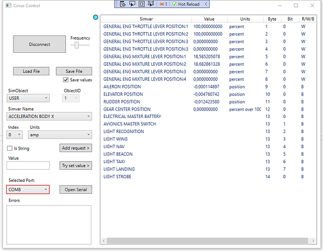
Yes, it takes the Data coming from the Yoke via UART and sends it to MSFS using simconnect.
It also works the other way around. I also do have the Gear indicator exported from Simconnect, sent to the Yoke.

The tool is not polished yet but it works. :smiley:
You can choose the value Variable, select the Byte and Bit Order and if it will be send/received or both.

The Protocol is dirt simple. Byte 0 is the Identifier, Byte 1-XXX is the Payload.
Analog Values are sent 1 each byte. Boolean Values can share a Byte (8 bit).

I had some thoughts about the FFB implementation. As there are sadly no direct Variables for the Forces on the controls in MSFS (Simconnect), you could theoretically use a quick and dirty version and calculate it from the relative wind velocity and Aileron/Elevator Deflection.

Same for the Rudder / Wheel Connection.

Here a Screenshot of my program. Currently flying a two engine aircraft at high altitude (mixture is at 18% :D). Still have to Add the calibration feature as this is a big con with this solution → you cant use the MSFS integrated calibration function (as far as I know). For this you’d have to have a HID Device…

All the variables can also be found here:

There are definitely FFB pedals from people like Brunner and also FFB home built pedal for other sims. Whether they work in MSFS, no idea.

http://bffsimulation.com/FFB-pedals-1.php

You know, now that I see what you have for the UART… I would have probably done the same. I’ll explain better further down.

My descriptor is 1287 bytes :grimacing: :grimacing: and I haven’t added anything yet. The complexity of USB to implement even the simplest thing is just astonishing.

Ok, this is really interesting, please help me to understand… because I had a very long discussion on the other thread about DIY controls and I was asking what protocol simconnect (was it simconnect? Or some other program to interface with MSFS? I can’t remember the name now…) used to transfer the data out of the UART, since I could not find it documented anywhere, and everyone refused to answer saying “it works with Arduino, just use it” :roll_eyes:
So, that program that you are showing, did you write it by yourself or is it a standard program? I really would like to make my own panels, but I have no way to talk to the simulator…