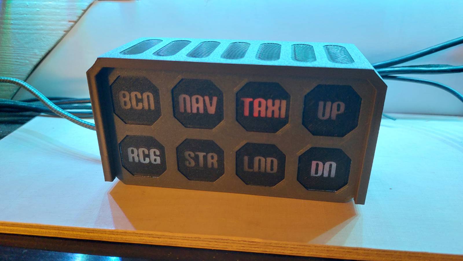
Hi, after my miniAVX was finished, I decided to get the lights and gear indicators “off-screen”.
Again, I am using BitsAndDroids, as the code is very minimal and I have this app already running. Mobiflight could also be used to make this work, but please do not ask me how, as I have no experience with it.
Parts List
6 pcs. LED white 3mm
1 pcs. LED green 3mm
1 pcs. LED red 3mm
8 pcs. Resistor 470 Ohm (others may also work, depends on the LEDs used)
1 pcs. Arduino Nano
STL files
The parts should be printed with dark colors to prevent light entering or interfering with the display. I used black for the Arduino cradle and the individual frames. The housing was printed in dark grey. And of course you need some transparent filament as well for the diffusors and front plates.
1 Like
Building instructions
Here is a picture showing how I wired this one. If you group the LEDs you can get away with a lot less ground cables (2).
Be careful not to get to much hot glue on the sides and on the top where the latches for the housing are. 
Finally, have a little strip of black tape ready to cover the LEDs of the Arduino Nano. Don’t worry, even duct-tape lets some light through, but its enough to shield the front LEDs from it.
Arduino Code
Pins 4-11 are used on the Nano. 10 and 11 are PWM pins, so the brightness can be changed (aka the gear is in transfer). Please check the first lines of code (starting at “const …”) to get an idea which pin is which. Odd is the top row of the panel, even the bottom row.
#include <BitsAndDroidsFlightConnector.h>
BitsAndDroidsFlightConnector connector = BitsAndDroidsFlightConnector();

const byte rcgPin = 4;
const byte bcnPin = 5;
const byte strPin = 6;
const byte navPin = 7;
const byte lndPin = 8;
const byte taxiPin = 9;
const byte dnPin = 10;
const byte upPin = 11;

void setup() {
  Serial.begin(115200);
  Serial.setTimeout(15);
  pinMode(rcgPin, OUTPUT);
  pinMode(bcnPin, OUTPUT);
  pinMode(strPin, OUTPUT);
  pinMode(navPin, OUTPUT);
  pinMode(taxiPin, OUTPUT);
  pinMode(lndPin, OUTPUT);

  lightsCheck();
}

void loop() {
  connector.dataHandling();

  digitalWrite(rcgPin, connector.getLightRecognitionOn());
  digitalWrite(bcnPin, connector.getLightBeaconOn());
  digitalWrite(strPin, connector.getLightStrobeOn());
  digitalWrite(navPin, connector.getLightNavOn());
  digitalWrite(taxiPin, connector.getLightTaxiOn());
  digitalWrite(lndPin, connector.getLightLandingOn());

  byte landingGearPercentage = connector.getGearTotalPct();
  //gear in transfer
  if (landingGearPercentage < 99 && landingGearPercentage > 0){
    analogWrite(dnPin, 0);
    analogWrite(upPin, 255 - landingGearPercentage * 2.55);
  //gear is down
  } else if (landingGearPercentage >= 99) {
    analogWrite(dnPin, 255);
    analogWrite(upPin, 0);
  //gear is up
  } else {
    analogWrite(dnPin, 0);
    analogWrite(upPin, 0);
  }
}

void lightsCheck(){
  lightsToggle(true);
  delay(1000);
  lightsToggle(false);
  delay(500);
  lightsToggle(true);
  delay(1000);
  lightsToggle(false);
}

void lightsToggle(bool state){
  int pin = 0;
  if(state){
    for (pin==4; pin<=9; pin++){
      digitalWrite(pin, HIGH);
    }
    analogWrite(dnPin, 255);
    analogWrite(upPin, 255);
  } else {
    for (pin==4; pin<=9; pin++){
      digitalWrite(pin, LOW);
    }
    analogWrite(dnPin, 0);
    analogWrite(upPin, 0);
  }
}
UPDATE!
I have created new masks versions (with or without test/reset button).
v1 is meant to be glued together, v2 is an all-in-one print.
I also added comments with recommend print settings.

")