As a Corona project, I realized a dream I’ve held for a long time, and built a GA panel. It mimicks the Diamond Katana DV20 panel because that plane is the closest to the one I learned flying on in a decade ago or so. I want to fly as realistically as possible - I’m not a millionaire so I will never fly a jet, or even a turboprop. Old school, VFR only flying, if there’s a GPS then only a handheld device, and the autopilot is optional. I already owned the Saitek Switch Panel, Radio Panel, AP panel, and TPM. I had them stacked on the desk but they kept sliding when I pressed buttons and all it all they looked like clutter.
My design goals were:
- Built from used parts as much as possible because I wasn’t so sure if I would be using it a lot.
- Real hardware knobs to set QNH, VOR1 and VOR2, HSI sync, and HSI course.
- Adaptable to other GA airplanes as well, including variable pitch propellers.
- Should fit under my monitor and not take a lot of space on the desk.
- Reduce clutter, not increase it (can be stowed away in one piece if not needed)
Parts I used and prices
- an old iPad 2 that I had kept for this purpose (yes, the 2011 one!) You can buy them used on private listings for 40 € or so since they are useless for anything else. Since the state of the exterior and the battery don’t matter for this purpose, you can really buy the cheapest one that you can find as long as the screen still works
- a laptop screen from a 12 year old Thinkpad laptop that I bought for 25 bucks or so online. After stripping it for the screen, I was able to sell the scrap parts for 15 Euros or so, so the screen cost me like 10 bucks iirc
- a separate control adapter card for the screen to power the LCD screen and provide video ports - 25€ and waiting 6 weeks for it to arrive from China
- a power supply to power the LCD screen - 15 €
- a Raspberry Pi 3A+, bought used off Ebay for 36 €
- an Arduino Nano to run the knobs and interface them to Air Manager for 12€ or so
- a high-quality USB hub for 30€ - I tried cheaper ones but they didn’t work reliably and caused CTDs
- the front panel - I designed it first on paper and then (because it became really complex) using a simple drawing program. Then I used an online metal cutting service to cut it from 3 mm Dibond which essentially is two layers of aluminum with a plastic layer in between. I chose it because it looks cool and provides stability while still being able to saw, cut, drill, and sand. This was the most expensive part at 86€.
- 3D printed Instrument bezels - I used allanglen’s models on thingiverse for the small ones but resized them slightly because I wanted all instruments to fit into the available screens. With printing you have to choose between cheap or quick - I think I paid 36 € or so for 16 round instruments and 4 rectangle ones that I had designed myself
- a 3-way multi-socket power adapter to power the Raspi, LCD, and USB strip wich in turns powers the iPad.
I had zero prior knowledge in any of these. I’ve been a computer programmer at the start of my career, but I’ve moved out of the field since, so I have some programming affinity which definitely helped. I love learning stuff and I had to acquire skills in Arduino concepts, 3D model drawing, simple CAD, vector drawing (do draw Air Manager instruments using InkScape), soldering (for the knobs and wires), crimping connectors (for the knobs), modifying LUA code (for adapting Air Manager instruments), so it was a great learning experience.
Lesson learnt regarding the panel
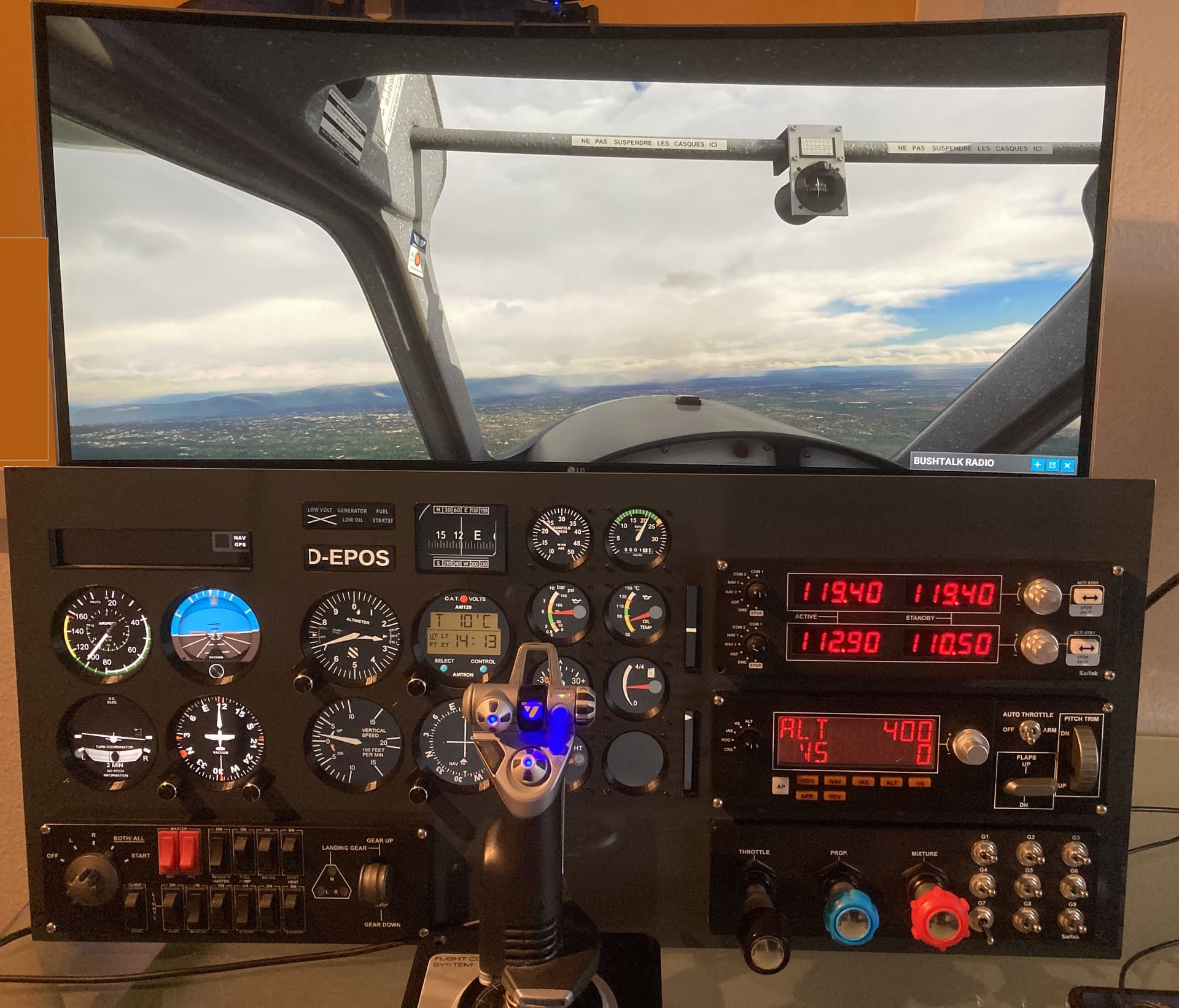
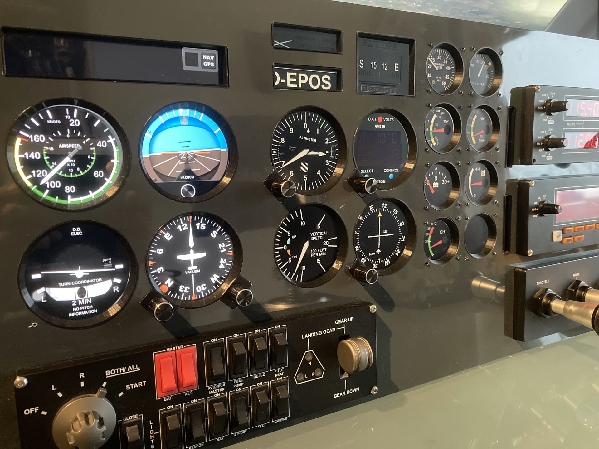
Drawing the panel was the most difficult part. I optimized for space comsumption because I don’t have the room to build an entire cockpit, I need it to fit under my monitor. The iPad and the LCD monitor have bezels that can’t display stuff, so the instrument cut outs had to reflect that. I wanted to cram all needed instruments into the available space so I used the screens to the last mm. The screen and iPad need space for the plugs to go into them, so you can’t just place them at the outer edge, etc. I’m surprised that it worked at the first attempt, but I’d say I spent 20 hours or more in total just drawing that panel cutout. It turned out great. I used a file to cut out the boxes for the knobs because it was just too complicated to design them into the panel directly. I caused some scratches and it was a tedious work so next time I would probably dry harder to have them cut by the cutting company instead of adding them myself.
I think it turned out great. The left 4 round instruments and the square one above are driven by the iPad. The others are driven by the LCD screen that’s more or less glued to the back side of the panel.
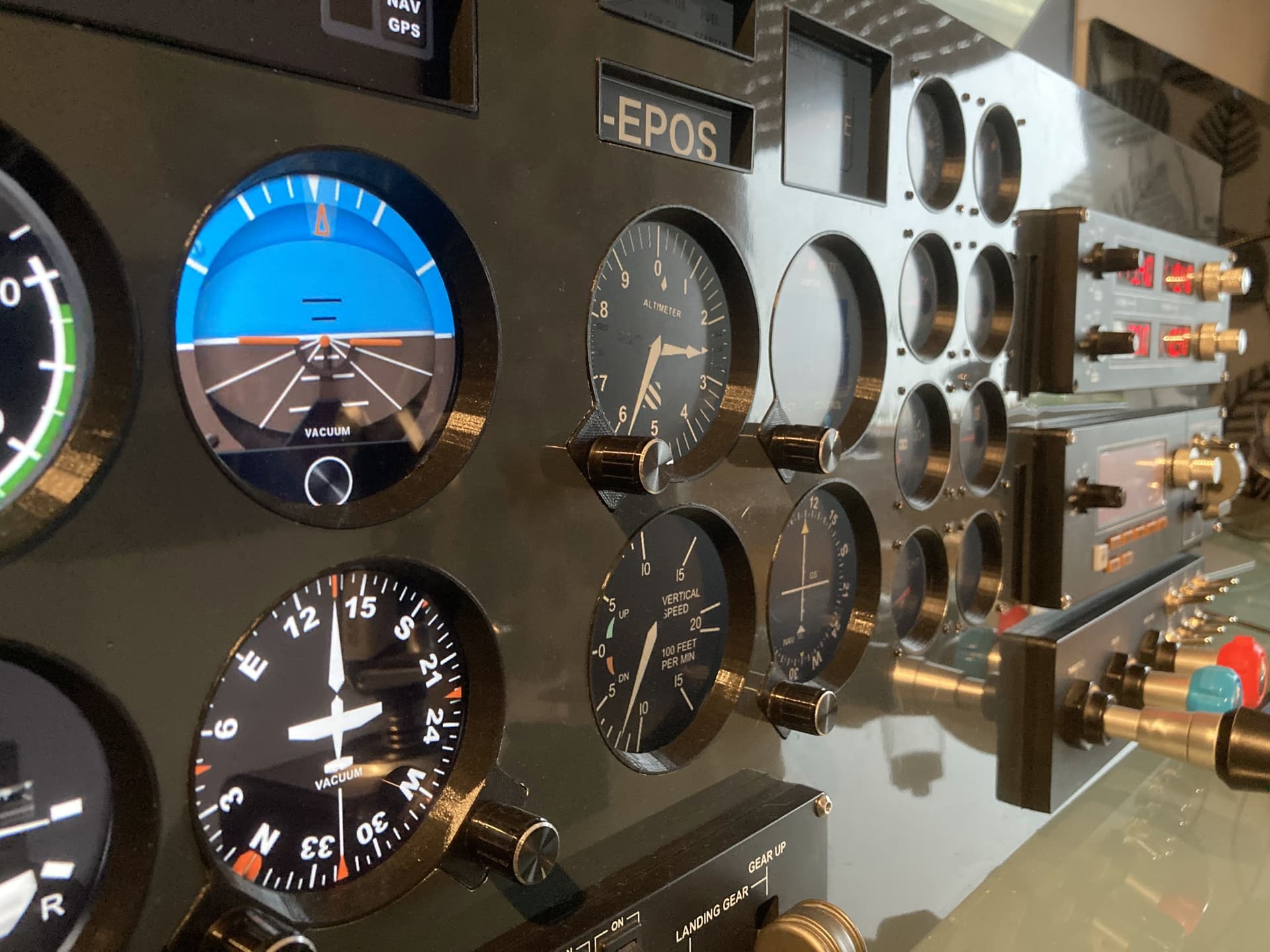
Since I had reduced the size of the bezels slightly, the cutouts for the rotary encoders shrunk as well, so I had to dremel them in order to fit the encoders into them (I could have changed the 3D file but my skills weren’t strong enough and I wasn’t sure about the size of the encoders anyway).
Repurposed LCD screen? not again
I wouldn’t do the LCD screen solution again. The screen itself is dirt cheap, but it’s an old and pretty bad screen. On old LCD screens the backlight gets much darker, so it doesn’t look very brilliand and I have to crank up the brightness which makes the black appear a little greyish.
I considered using an old monitor instead, but the old ones I found are clunky and heavy and I wanted to be able to stow away the cockpit when not in use.
Also, the screen itself might be a steal but all the stuff you need to drive it isn’t, and it adds up. You have all the parts flying around without a casing, so I had to get creative to fix them on a piece of wood and glue them to the back of the screen. The screen doesn’t switch on by itself when the power supply is plugged in, so I had to mcgyver a button to switch it on that I still haven’t fitted into the panel.
All in all, next time I would choose either a portable USB screen or go with an external monitor and accept the added weight and bulkyness.
iPad - 5/5 would do again!
The iPad looks great and is a very elegant solution because it only requires one cable and is very flat. The only problem is that if it’s built into the panel you can’t access its side buttons to unlock the screen and so on. The solution I found was “guided access” it’s built into iPad OS even for the old iPad. The nice thing is that when the iPad USB is plugged in it powers up the device and unlocks the screen like in kiosk mode, so by powering up the whole panel the iPad comes up unlocked and displays Spacedesk. It’s a free app that extends the iPad screen to become a second small monitor from the PC’s point of view. I wanted to used it for the prototype only and run the Air Manager iPad app later. However, I’m staying with the spacedesk variant for now. The reason is that when the iPad acts as a second screen to the PC, it can display any instrument that Air Manager is capable to drive, while in the iPad app there’s only a fixed set of gauges you can use and you can’t add your own.
The art and science of gluing
The other part that turned out surprisingly difficult was the gluing. I used double-sided adhesive tape but the stuff fell of after a couple of weeks (in the middle of the night, obviously). Aluminum (Dibond) as well as the plastic parts require special tape that I had to find and order, not it works ok but still feels a little flimsy. I searched for a solution to glue the screen to the back of the panel for ages, and finally I set with an edge profile for laminate floor that can not only hold laminate but also a 9 mm thick LCD screen.
Small stuff adds up
Another thing I was surprised about was the hidden cost of all the seemingly minor parts.
- Order adhesive tape - 8 Euros.
- Falls off after 2 weeks. Buy better tape for 12 €.
- Screws to hold the instrument bezels in place - 8 € inkl. postage on Ebay.
- Screws are much too small (what have I been thinking?) Buy larger ones - 8€ again.
- I have to screw the Arduino and LCD electronics onto the plywood sheet - mainboard holders, 10€ a box on Amazon.
- ruined an encoder while soldering (soldering is not my strong suit) - buy new ones, only 1,70 € a piece but 6 € postage and wait 4 days for them to arrive
- Cables to connect the rotary encoders to the Arduino look awful and come off a lot. The solid solution would be to get a connector board and connectors, but you have to crimp them yourself. Crimping tools are freaking expensive, bought a 22€ one that is pretty good.
- Oh year, connectors - 12 € a box on Amazon.
- Nope, those don’t fit onto the board. Find better ones, another 15 € on Amazon.
It gets much better if this isn’t your first project, but if you’re like me and you’re starting from scratch, collecting all the small stuff that’s needed costs a lot of time and money. I now have a box of boxes of which I have used almost nothing at all (connectors, Arduino parts, wires, screws, tape) etc, so I have to build another panel just to use more of that stuff lol.
Looking for ideas for the box enclosure
The project is finished now. It looks great from the front but awful from the back. I still haven’t found a solution for the enclosure yet. I asked a local woodworking company if they would build me a simple box but they didn’t respond. I’m a bit out of ideas what to do with that last step. I could build a box myself but I have no woodworking equipment whatsoever and I don’t want to get into the business just for that simple box. I tried local wood cutting services but none of them will cut the groove that I would need, not even the highly specialized ones that build kitchen countertops etc. As a last resort, I could have the boards cut and dremel the grooves myself, but as far as I have learned so far on Youtube university, that’s too much to handle for a little Dremel and will look bad.
Final verdict
Flying with it is great fun. It really adds to the immersion immensely to be able to adjust the QNH and compass sync using real knobs. It extends the screen space considerably if you don’t have to display the instruments. Together with my TrackIR, it’s very immersive and realistic.