I’ve tried getting an answer on other forums but no luck. Hoping some friendly PC builders here will help.
I have a Legion gaming desktop (34IAZ7 Model 90S10006US) that came with an 850W FSP PSU. I had upgraded my GPU from the 3080 to a 3090 and now a 4090 and wanted to upgrade the PSU as well. I bought a Thermaltake GF3 1200W ATX 3.0 PSU that fit, but wouldn’t power up. Verified it wasn’t dead with the paper clip test, but couldn’t get the machine to power with either the old or the new 24-pin.
I reached out to Thermaltake and they basically said, 1) That won’t work and 2) You’re an idiot for trying. No explanation why. So I’m wondering if I try another PSU, even another FSP, how do I know it will work? The 4090 is running fine, BTW with the 3x 8-pin adapter, but I think I want to be safe and upgrade the PSU. Thanks for helping an idiot out. LOL.
What warning indicators are you getting when you try to power on ?
Try powering on with out the gpu installed to see if you get the correct error.
Have you tried the old 850w PSU to see if the board is receiving power?
Basically try some swapping out with the kit you already have to see if it will give you an error message you can work with.
Hi - thanks for the reply. With the Thermaltake PSU, the computer is completely dead, so no error codes. I understand the PSU waits for the motherboard to jump the right connection before powering up and with Lenovo, it must be different.
I had a similar problem when trying to replace the 3x-8pin PCIe cables feeding the Nvidia 4090 via their 12VHPWR adapter. Tried to replace it with a 3x-8pin to 12VHPWR Cablemod cable for a cleaner look, but apparently, the pinouts on PSUs are different and even though everything plugged in nicely, the computer would not start. Went back to the three separate cables and the Nvidia adapter which works fine.
I thought PCs were full of interchangeable parts. How do builders figure out what works with what?
If the PSU springs to life with the paper clip test and it is powering up OK it may be only the cable connections to the PC.
The only thing I can think of is, a while back, with those 12VHPWR connectors, if they weren’t fully home on the GPU the sensings pins ( 2 off ) on the plug would not properly make a connection and the PC would not start.
I am not recommending you force the connection onto the GPU socket, but I have read that some of them provided by the manufacturer wouldn’t even fit correctly as they were too tight, the retaining clip underneath should be locked in.
P.S. There was once a problem when swapping cables in a modular PSU from other manufacturers could be fatal, but I think that was sorted years ago, dont quote me on that.
You know that the cabling that comes with each PSU is proprietary? You cannot use cables from one PSU with a different one. There are a few that share the same pin in/pin out, but it is much safer to just use the cables that are supplied with the PSU. Using the wrong cabling can damage components and/or the PSU. Article on this here.
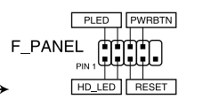
What exactly do you mean by the paperclip test? I sincerely hope you mean that you shorted the front panel power button pins.
The best way to check a PSU output is with a multimeter. There is an extremely good guide on how to use a multimeter here. Some boards have inspection points to verify voltages being used on the board. Asus use the term probelts.
Does your board have an error code digital display? If it does not then all PCs should come with a beep code (AKA post code) function. You ofc need a speaker connected to hear this. Unaffiliated amazon link here. Beep speakers can be bought from many places. Amazon are not the only vendors. Search for beep, bios or post speaker.
You will need your motherboard manual to show you where to connect the speaker to, and to understand what the beep code means. Motherboards vary in the layout design and error code outputs.
This is important info for me personally. I just bought an EVGA G7 1000W PSU to replace the EVGA G6 850W unit I currently have.
Under full load while benchmarking my system is drawing about 760W. I know that’s under the current P/S 850W rating, but I’m going to feel a lot better having the extra 250W headroom.
I was planning to leave all my cables in place, and just swap the units. Now you’ve got me thinking that might be a huge mistake.
I’m going to email EVGA support and ask them about cable compatibility between the G6 and G7 series. I may even test the PSU voltages myself, just to be sure.
Thanks for the link that explains the right way to test them.
Very smart to have headroom, GamersNexxus has shown there are spikes that no software monitoring can catch
Well, I certainly learned that. I understand it is what it is, but it’s seems strange that there is a standard connector, like the 8-pin PCIe that everyone uses, and I assume the pinouts on the component/GPU side are a standard, but the 8-pins on the PSU side are all over the place and they’re mostly sending +12V or Ground.
Bascially bypassing the motherboard so that the PSU turns on.
@kjacrobat One I did not know about.
Yes it is a much easier option over learning the pin out with a multimeter. One I will remember for future recommendations.
AS you have discovered, despite appearances, PSU are not plug and play, even within the same brand you cannot always just plug a new modular PSU in and retain the old cables. It is not just the pin outs that vary but also what connectors connect to the same or different rails internally.
The mother board end is reasonably standard for generic PCs and usually swapping in a higher rated name brand PSU is not an issue but that can also vary, especially for commercial name brand PCs. Replacing the PSU in a HP Desktop for example, you may have trouble physically getting a standard ATX/SFX to even physically fit and the motherboard connections are usually totally different.
If you know what you are doing you can download the technical/wiring specs for the two PSUs and if necessary pull out the soldering iron and heat shrink and create a bespoke custom cable mixing and matching connectors BUT do not attempt this unless you know exactly what you are doing as “try it and see” is a very bad plan with power supply wiring.
Follow up. EVGA said this:
The pinouts for these PSU are the same besides the SATA cables. i would recommend changing the SATA cables when changing your PSU.
That’s not bad. At least I don’t have to route new mainboard and GPU power cables. SATA power cables are pretty easy.
Thanks again for the important tip about not assuming all pinouts are the same.
@FlyerDreamerNJ PC manufacturers (as opposed to system builders, who use standard parts) are notorious for making connectors and parts non-standard to prevent you from using different parts. They want you to buy upgrades from them only. This can extend to the motherboard power connectors etc, even if they look standard they may be wired differently. That said, the connectors will still be carrying the same voltages / signals, so it is often technically possible to make adapters that would connect standard parts to non-standard boards.
However - the info I can find with a quick Google says that the T7’s PSU and MB connector is standard ATX, so what you are doing should work. You need to get Thermaltake to explain why they think this won’t work. Just because it’s ATX 3.0 shouldn’t mean it won’t work on an ATX 2.x board. If the PSU will still spin up now when you short the switch pins, then you can’t have killed it by using the old FSP cable (but, as others have pointed out, never ever attempt to re-use PSU cables except from the same manufacturer and range, and even then, check compatibility on-line or better still, just don’t do it at all).
It seems like maybe the T7 MB is not shorting the pins when you press the power-on button. You could tap the relevant pins on the socket on the board (per the ATX spec) and check for continuity with a multi-meter when you press the power-on button. If the pins get shorted and the PSU powers up when you short those pins on the PSU side, then it has to be some other signal that’s preventing it from powering-up, and I’m not aware of what that could be; but I have no ATX 3.0 experience.
Thanks for the detailed reply! Yes, Thermaltake wasn’t very helpful. It just may be that they don’t want to deal with PC sellers if they don’t have a deal with them. I’ve already returned the Thermaltake PSU, so it may have been something other than the 24pin.
So, I’m back to the 850W FSP that originally came in the T7 - it has 3 PCIe connections for the GPU, but only used two from the factory. I had some really dumb luck (emphasis on dumb based on what I know now) in that I tried another PCIe cable that I found (before I knew they could be different based on mfg) and it worked. I tested it with a multimeter and compared it to the two existing PCIe cables, and while the pinouts were different connector to connector, the output to the GPU was the same – all ground near the clip and +12v along the top except for the last pin which was ground. The 12V pins and ground pins were in a different order within their “group” (if that makes any sense), but the end result was the card is running fine. Dumb luck, for sure.
So, for now, I’m good. Fingers crossed, I won’t be going back inside this box for a while. Thanks to all for the education! Really appreciate the help!
Not to be at all political as I’m US based but we really need the EU to get on this and standardize more PC stuff (like PSU pin outs)… I only call out the EU because of their success even daring Apple to back down RE:USB C
That will likely introduce more issues than it solves as despite the impression that all PSU are the same this is just not true. It would likely, for example, have made the new NVDIA GPU power connector illegal.
It’s worth noting that there are reasons for the PSU pinouts to differ. Different OEM’s have different design practices, such as how many voltage rails to use, efficiency targets, and signal quality. The internal design of the PSU can be changed up to meet various design goals, which means the connections are not always going to line up the same. I get the argument for a standardized pinout from the PSU side, but doing so would require tradeoffs. I.e. More cluttered internals jumping connections around, reduced performance, lower efficiency, etc. Or simply increase prices to cover the added development costs to keep performance up.
So the question is do we want to sacrifice performance or increase prices for that? The compliance cost alone is likely to increase prices even if a manufacturer is already compliant with no changes. They still have to go through a certification process, and updated package markings to advertise their compliance.
Here’s an interesting Gamer’s Nexus video interview with former PSU reviewer (now Corsair engineer) Jonny Guru, in which they discuss the genesis of modular cables, how they led to the non-standardized power cable pinouts, and a lot of other technical tidbits about PSU design.
This isnt about OEM pinouts, it’s about modular cables and their connection to the PSU being different.
I haven’t bothered to touch an OEM pinned machine since a hot garbage Pentium II 300
Have to disagree here in some parts. The internal design of the PSU has nothing to do with the layout of the pin out. The main reason being that they all have to connect to the same hardware within the PC build. Gamers Nexus did some great videos on PSUs and what goes into their make up.
The main reason the pin out differed was because of litigation over copyright. I am fairly sure that the video @BegottenPoet228 links states this.
I do agree that there would be a cost to alignment for pin outs that differ to an accepted platform, but then they would not sell many PSU if they were identified as being off standard. It would be a cost that they would have to endure just to stay in business.