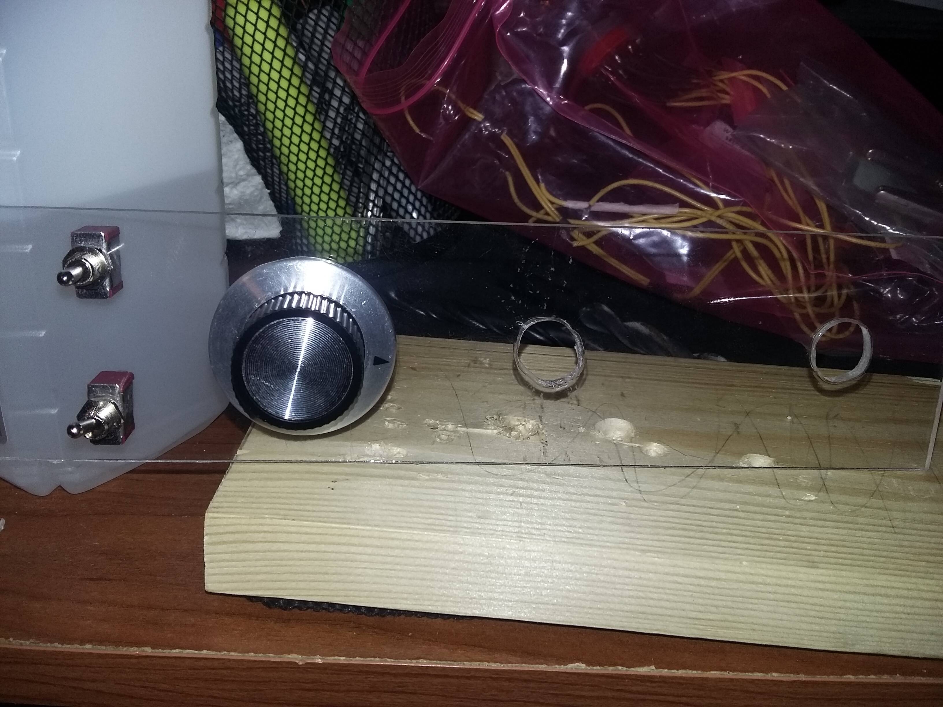
I’m working on building a throttle quadrant based around a pro micro and I already wired it up prior to the creation of the faceplate for a test run and it runs okay. As for physically creating the finished unit I can’t quite figure out how I need to mount this sliding potentiometer.
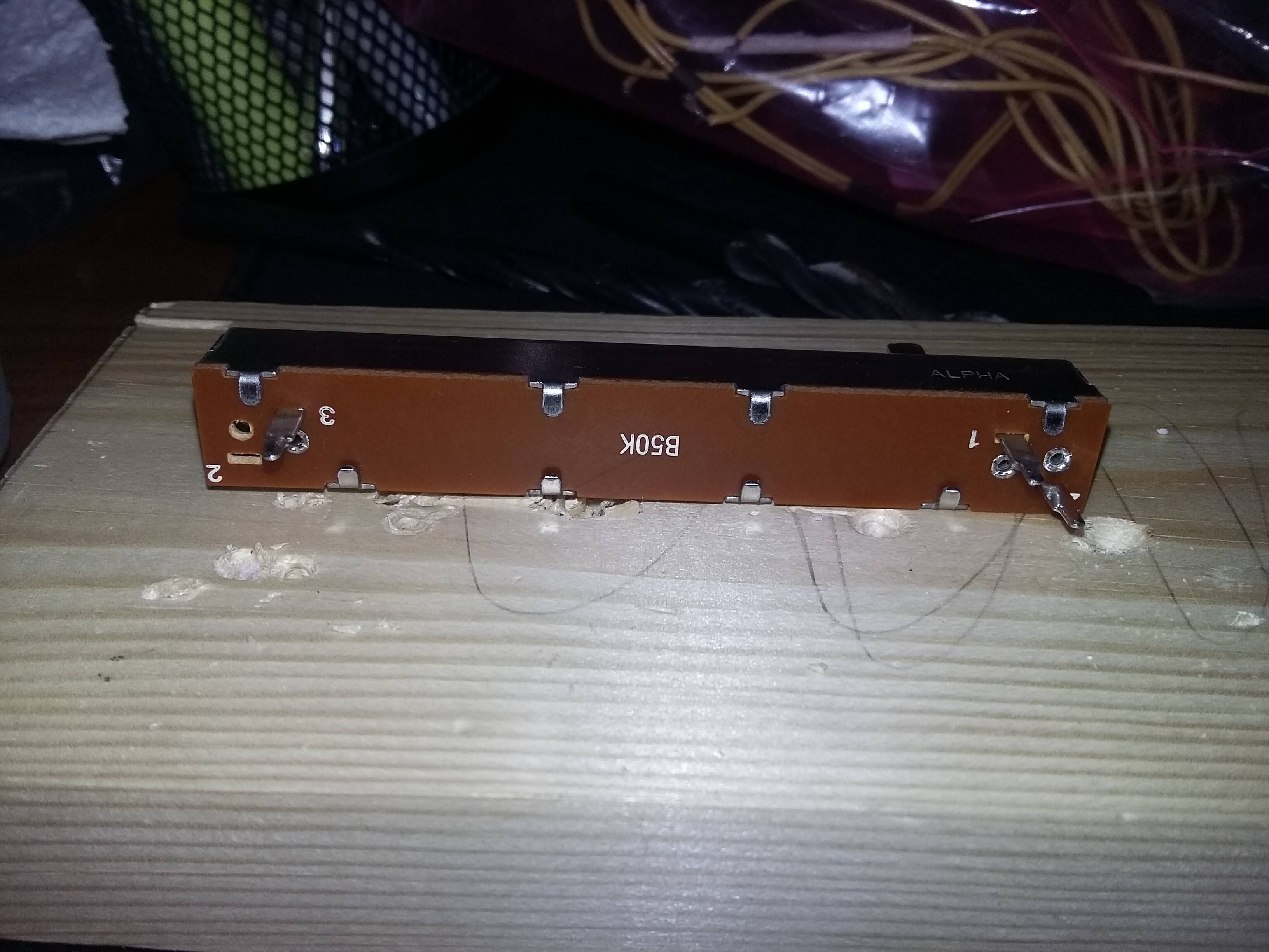
I’d like to mount it with shaft facing up so I can use a wooden dowel through the hole like a stick throttle. Looks like I might have clearance issues with the solder legs leaving no room for wires coming off the bottom of it. I noticed right beside the legs are metal “ports”. I checked them with a multimeter and they seem to be the same electrically as the solder legs. Are these alternate solder points I can use so I can clip off the legs or am I misunderstanding what they’re used for?
You must use the point 1-2-3 to solder some wiring; the other 8 bended are just for fixing the plate to the housing; if you need mountingspace : solder the wires to the bottum of the legs and cut the rest.
Cut a slot in the faceplate to accommodate the slide button. Fabricate and attach two pieces of material on either side of the slot, wide enough to nestle the potentiometer into. Super glue the pot into the supports. Maybe…
Those terminal lugs can be carefully bent over or just mostly cut off if you need more clearance. You only need a stub to solder to. Those terminals stock are long so they can stick through circuit boards for through-hole mounting.
If you bend them over, be sure to support them with some needlenose pliers or something so the phenolic and internal connections don’t have to take the stress while bending.
I made a small throttle quadrant a few months back using similar potentiometers. The numbered tags were 1- +5v/ +3v, 2- Analogue read, 3- Ground. 3mm screws can be used to fasten it to a plate and measure your sliding part for a push on knob they are usually 4mm or 8mm wide. If you need a sketch for your pro micro I can send you the sketch I have.