ANOTHER EXPANDED HONEYCOMB BRAVO THROTTLE QUADRANT CONFIGURATION
I modified the default MSFS Honeycomb Bravo Throttle Profile to achieve the configuration described below. It is a combination of features that I originally came up with along with additional features inspired by the original post from the author of this topic. My goal was to enable the Bravo’s right side adjustment knob to operate as many of the virtual cockpit knobs as possible.
THIS IDEA
The role of the left side function control knob and some of the top Autopilot Mode buttons have been expanded by making use of four of the seven mid-level rocker switches as mode controls. The right side rotary encoder knob continues to be used to increase or decrease values of those parameters selected by the left side knob.
AP MODE MODE
Bravo controls function as they were with the default profile when rocker switch #1 (counting from left to right) is placed in the bottom position which I refer to as the “AP Mode”. Except that when the left knob is placed in the CRS position either the OBS for NAV1 or the OBS for NAV2 can be controlled
as set by rocker switch #2 which functions as a NAV/COM unit selector. Its bottom position selects NAV/COM unit #1, and top position selects NAV/COM unit #2 for control.
NAV/COM MODE
When rocker #1 is placed in the top position, which I refer to as
the “NAV/COM Mode”, those parameters selected by the left knob are expanded to
enable control as follows as follows:
Position Control Parameter
ALT - Altimeter setting.
VS - COM whole frequency values.
HDG - COM fractional frequency values (no carry).
CRS - NAV whole frequency values.
IAS - NAV fractional frequency values (no carry).
In addition functions of the top Autopilot VS and IAS Mode buttons have been modified so that in this Mode the VS Mode button swaps COM frequency and the IAS Mode button swaps NAV frequency. Here again the NAV/COM unit under control is set by rocker switch #2.
ADF MODE
With rocker #1 placed in the bottom position, rocker #3 placed in the top position sets
“ADF Mode” where the left knob can be used to enable control of ADF frequency as follows:
Position Control Parameter
ALT - 100KHz digit (with carry).
VS - 10KHz digit (no carry).
HDG - 1KHz digit (no carry).
In this mode the Autopilot IAS Mode button swaps ADF frequency. However it is important to remember that rocker #1 must be placed in the bottom position for this Mode to work.
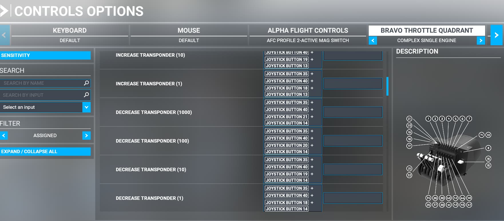
TRANSPONDER MODE
The top position of Rocker switch #4 sets “Transponder Mode” when rocker #1 is is also in the down position, In this mode the left knob enables control of Transponder code digits as follows:
Position Control Parameter
ALT - 1000s digit
VS - 100s digit
HDG - 10s digit
CRS - 1s digit
I would have liked to employ one or more of the Autopilot mode switches as operational controls such as IDENT, ON, or STANDBY. However I could not find command variables available within the MSFS profile to control them. I was able to employ a momentary button on another control device as an IDENT button using FSUIPC7 which made that command variable available. A Bravo Autopilot Mode button could have been used if I knew how to use switch combinations in FSUIPC7.
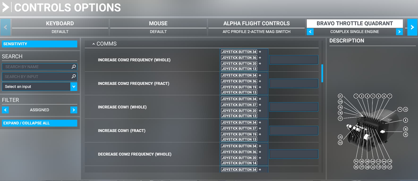
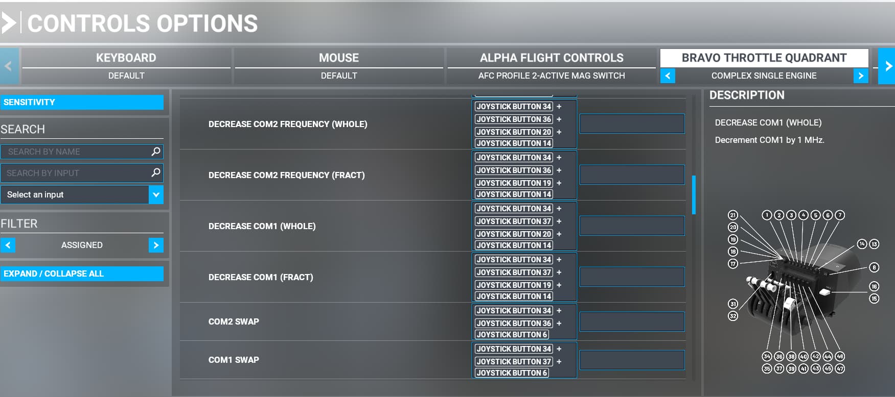
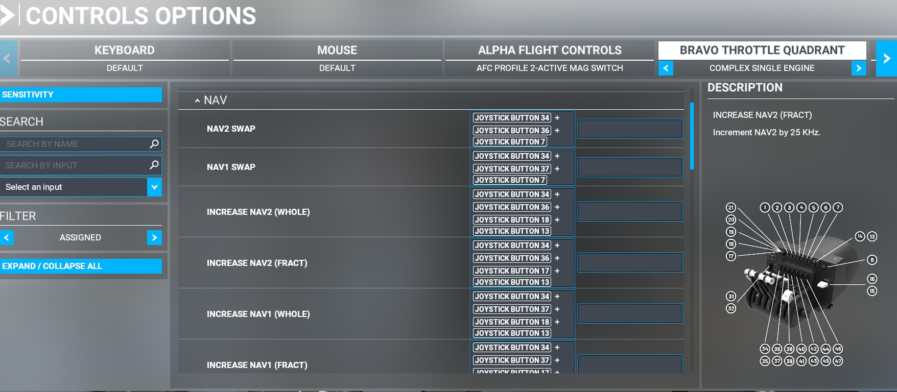
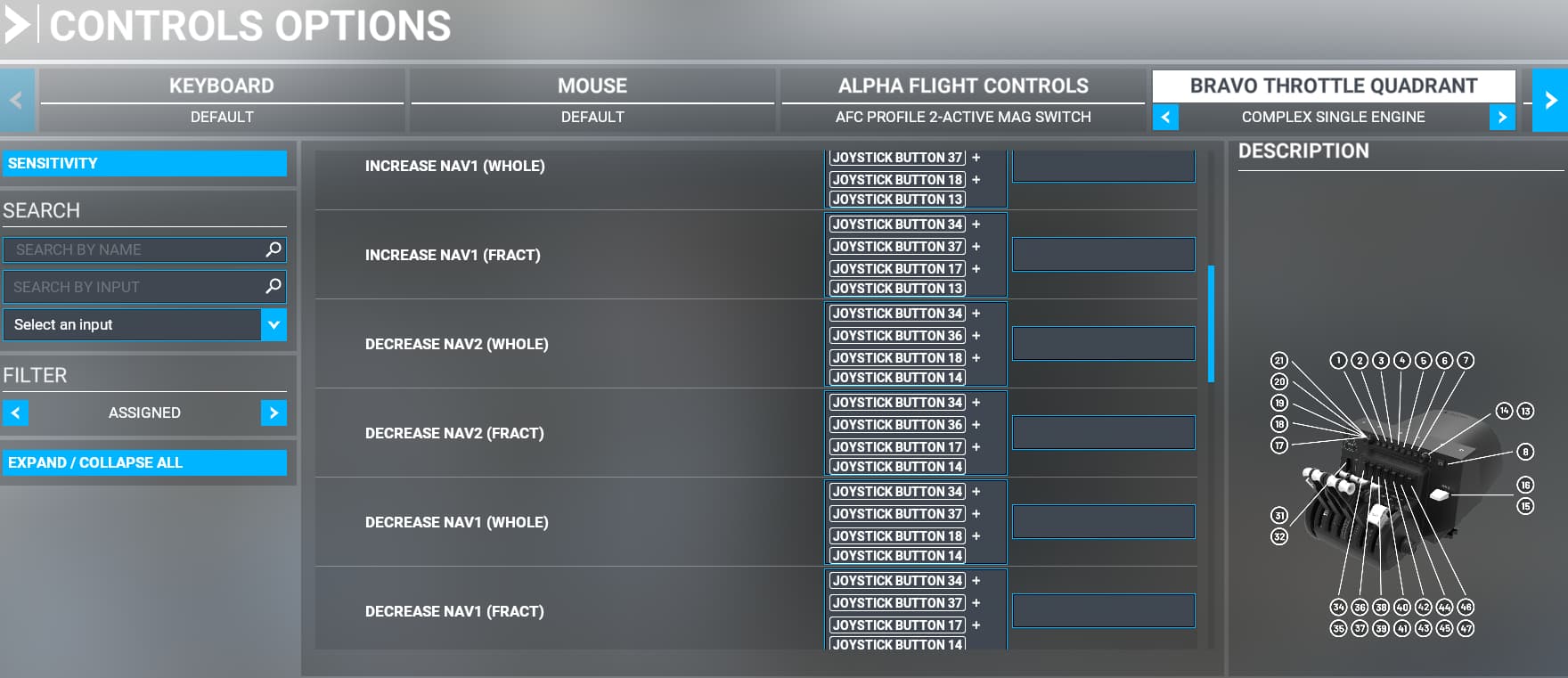
CREATING THE BINDINGS
Implementing the above configuration involves creating many new bindings in the Honeycomb Bravo Throttle Quadrant Profile. Making these bindings is time consuming, error prone, and just a bit tricky. I found this video available at Custom Switches for Honeycomb Bravo Throttle Quadrant in MSFS 2020 - YouTube to be most helpful by
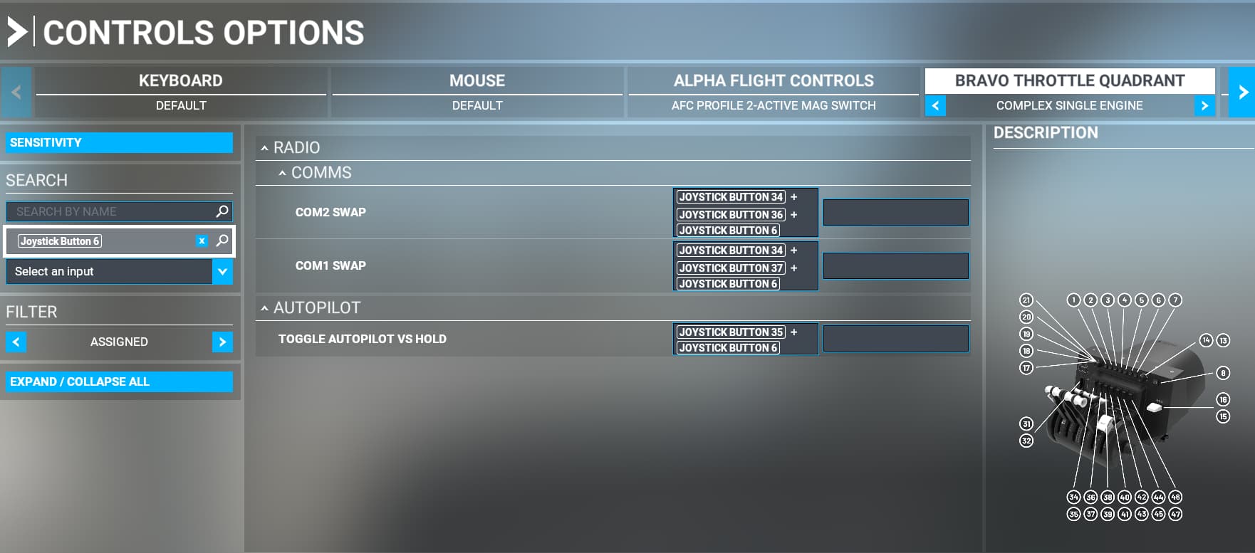
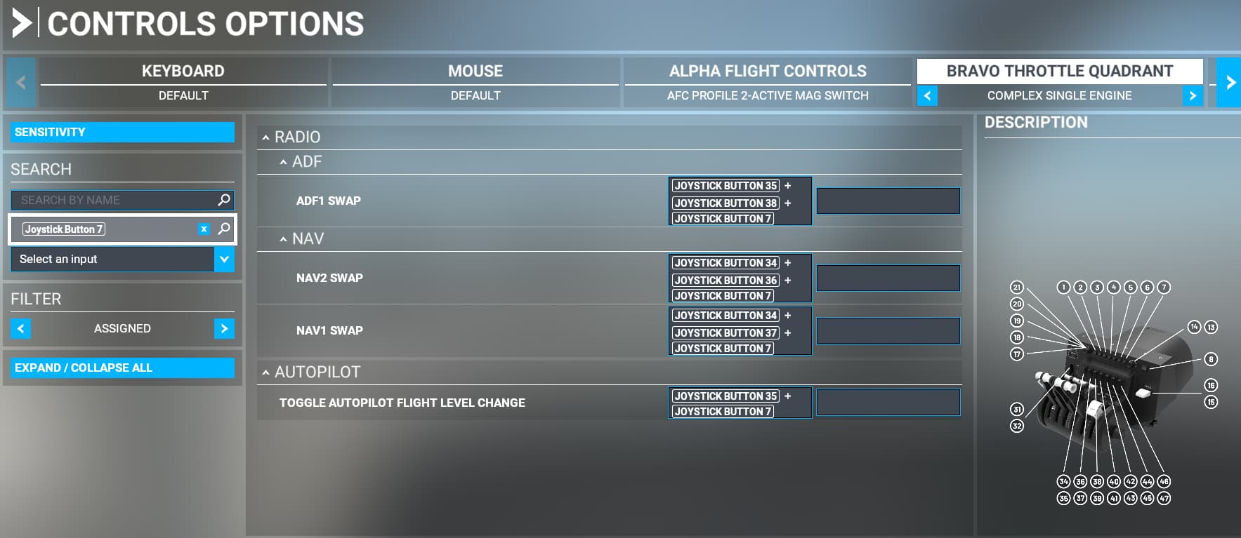
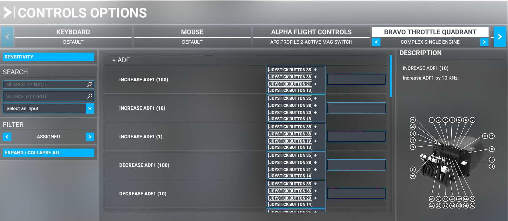
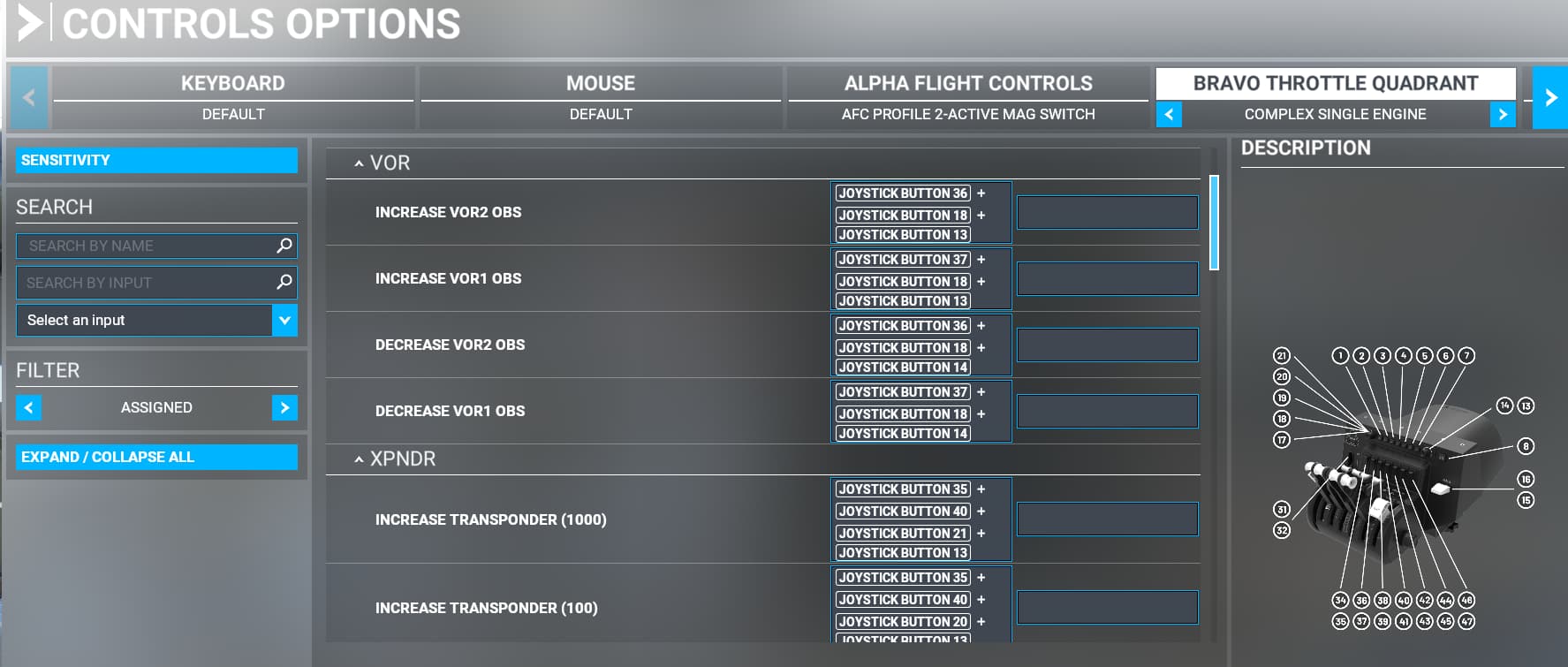
demonstrating this process. In particular at about 11 minutes into this video the author, Rmag, describes his bindings to control the OBS for VOR2. This example clearly shows how multiple switches can be combined to trigger an event which is the key to expanding the Bravo’s configuration. Attached below are screenshots of the bindings needed to implement this configuration as they appear on the CONTROLS OPTIONS screen within various sections of an expanded BRAVO Profile. They each include a diagram of the Bravo Throttle Quadrant illustrating the switch numbers assigned to each Bravo control that are used to create each of the bindings