I was one of the few people fortunate enough to secure an order for the Honeycomb Bravo when it launched back in December 2020. Since then, I’ve been constantly tweaking my setup for the most ideal mapping that is easy to use with the least amount of preset changes. (Hopefully, once Asobo implements aircraft specific presets, this will become much easier.)
Anyhow, I love both my Alpha and Bravo a lot, but I was a bit disappointed with the default configuration that the Bravo switches were set to by MSFS. A lot of them were duplicated from the Alpha, and some of them didn’t quite ‘feel right’ for the aircraft I was flying.
The autopilot panel especially took a bit of time to get used to; I’ve seen a lot of mixed opinions about that specific implementation.
A few days ago, I was messing with my configs and I realized, there are a lot more advanced setups you can do with the Bravo buttons and switches. This post is a configuration guide for the Bravo switch/button panel that I’ve set up to provide me quite a few extra controls in my hand.
The following config setup uses switch combinations for the controls - so please be careful while assigning. It is a pain to set it up initially (mapping mistakes take time to fix and remap), but was well worth it for me as the end result is super useful. Anyway, enough talk, let’s start tweaking!
Idea
Idea
-
We will be using a 1-hot encoding of the 7 unmarked switches to set the ‘mode’ of the Autopilot panel. 1-hot encoding means, at any time, only one of them will be ON, rest needs to be OFF. E.g., flicking switch 7 ON can set the ‘mode’ of the above buttons to Autopilot, switch 6 ON can reconfigure the above buttons to control radios and so on.
-
The left Knob on the Autopilot panel will select ‘functions’ in the set ‘mode’. E.g., in Autopilot mode, it selects ALT bug, HDG bug, etc. while in some radio mode, it selects the whole and fractional parts of the frequency.
-
The right Knob will be used for incrementing and decrementing the ‘function’ values.
-
The middle push buttons will be used for any ‘activate’ actions.
Autopilot
Autopilot
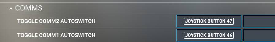
Autopilot mode is selected by setting Button 46 (switch 7).
As you can see below, every flight instrument selections and Autopilot mode toggles are modified as a combination of Button 46 and the respective buttons. You can set it up according to your autopilot configuration.

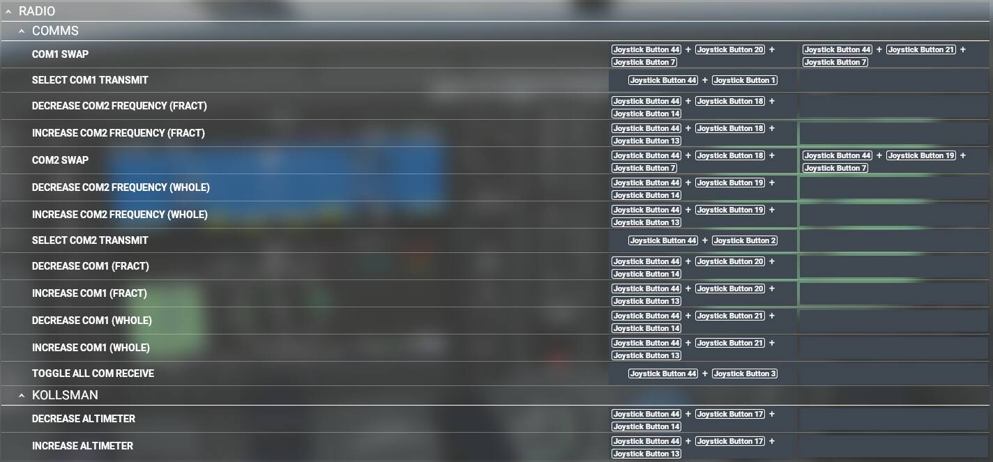
COM Radios and Altimeter
COM Radios and Altimeter
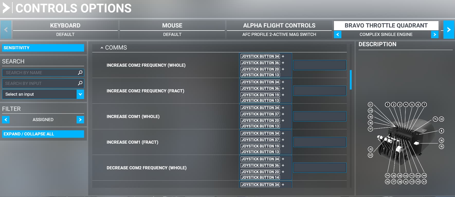
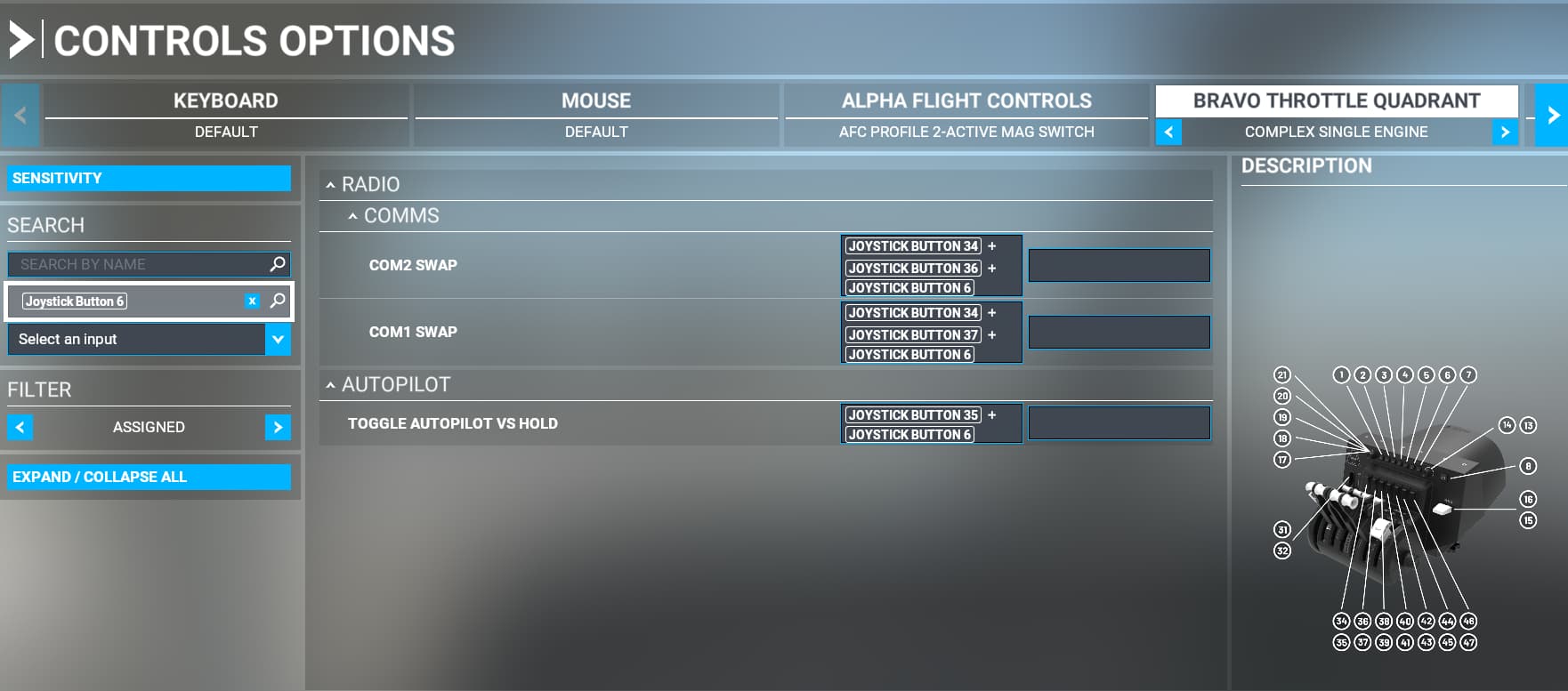
COM1, COM2 and Altimeter mode can be selected by setting Button 44 (switch 6).
COM1 function is selected by positions ALT (whole) and VS (fractional) on the left Knob.
COM2 function is selected by positions HDG (whole) and CRS (fractional) on the left Knob.
Altimeter function is selected by position IAS on the left Knob.
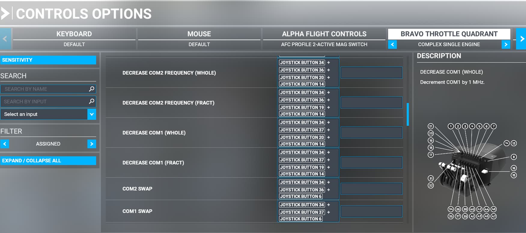
Increment/Decrement is with the right Knob as usual.
Swap standby ⇄ active with IAS button. COM1/2 depends on the position of the left Knob.
(Because there is actually no SELECT for these things, note the triple button combo for some of these.)
Transmit+receive on COM1 by pressing HDG button.
Transmit+receive on COM2 by pressing NAV button.
Toggle simultaneous receive on COM1+COM2 by pressing APR button.
Just to give you an idea about the mapping - e.g. Incrementing Altimeter is a combination of the following buttons:
Switch 6 (Joystick Button 44) + Left Knob at IAS (Joystick Button 17) + Right Knob Incr (Joystick Button 13)
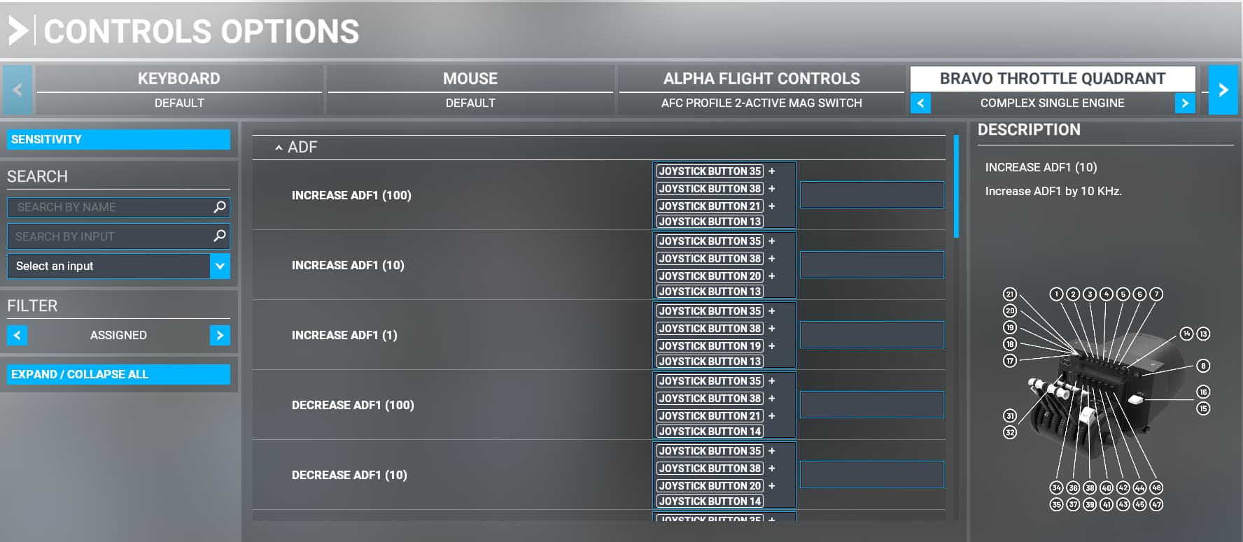
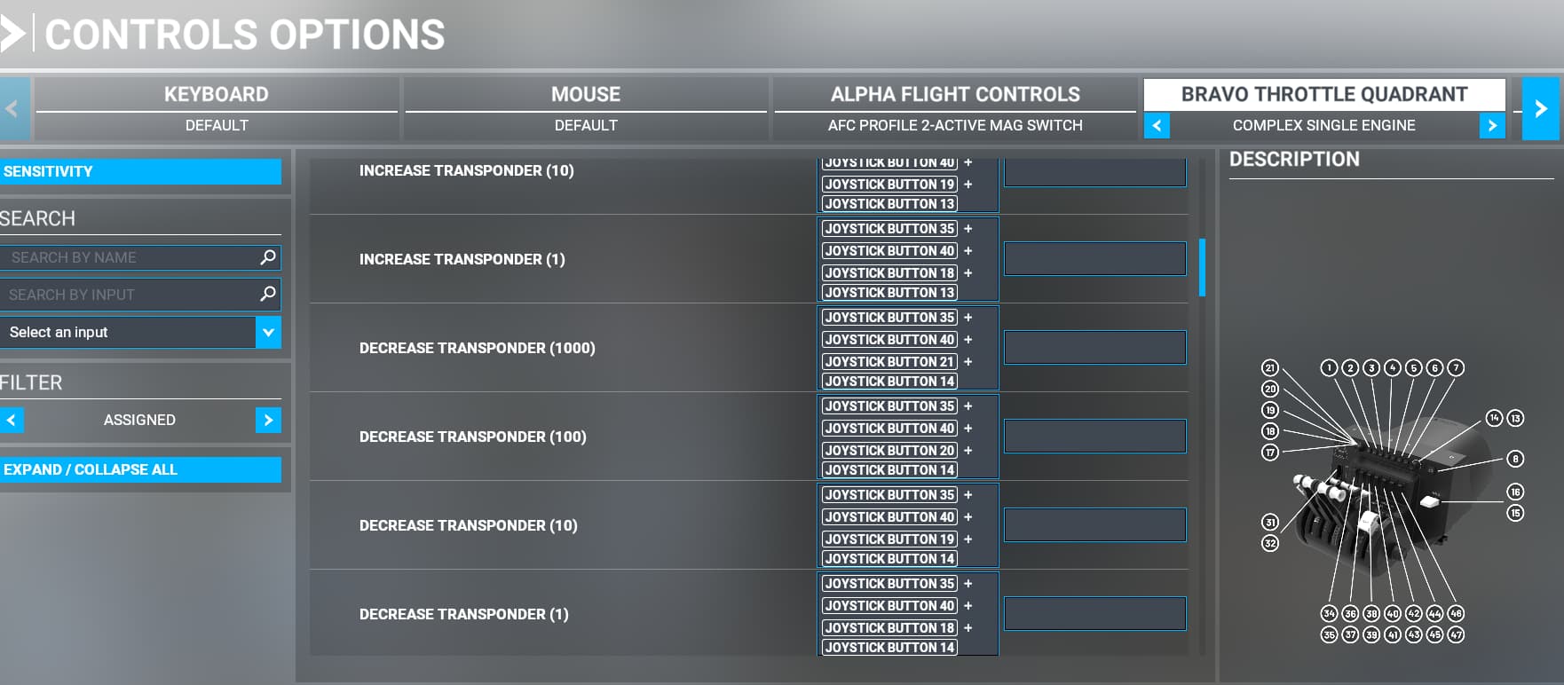
Transponder
Transponder
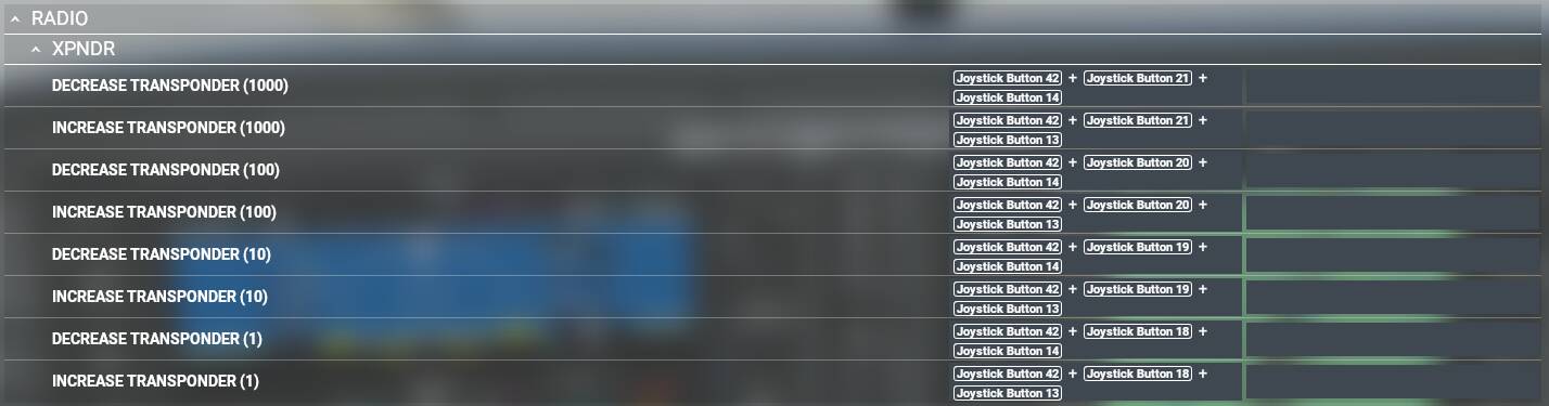
Transponder mode is selected by setting Button 42 (switch 5).
1000’s place select by left Knob in ALT position.
100’s place select by left Knob in VS position.
10’s place select by left Knob in HDG position.
1’s place select by left Knob in CRS position.
Increment/Decrement is with the right Knob as usual.
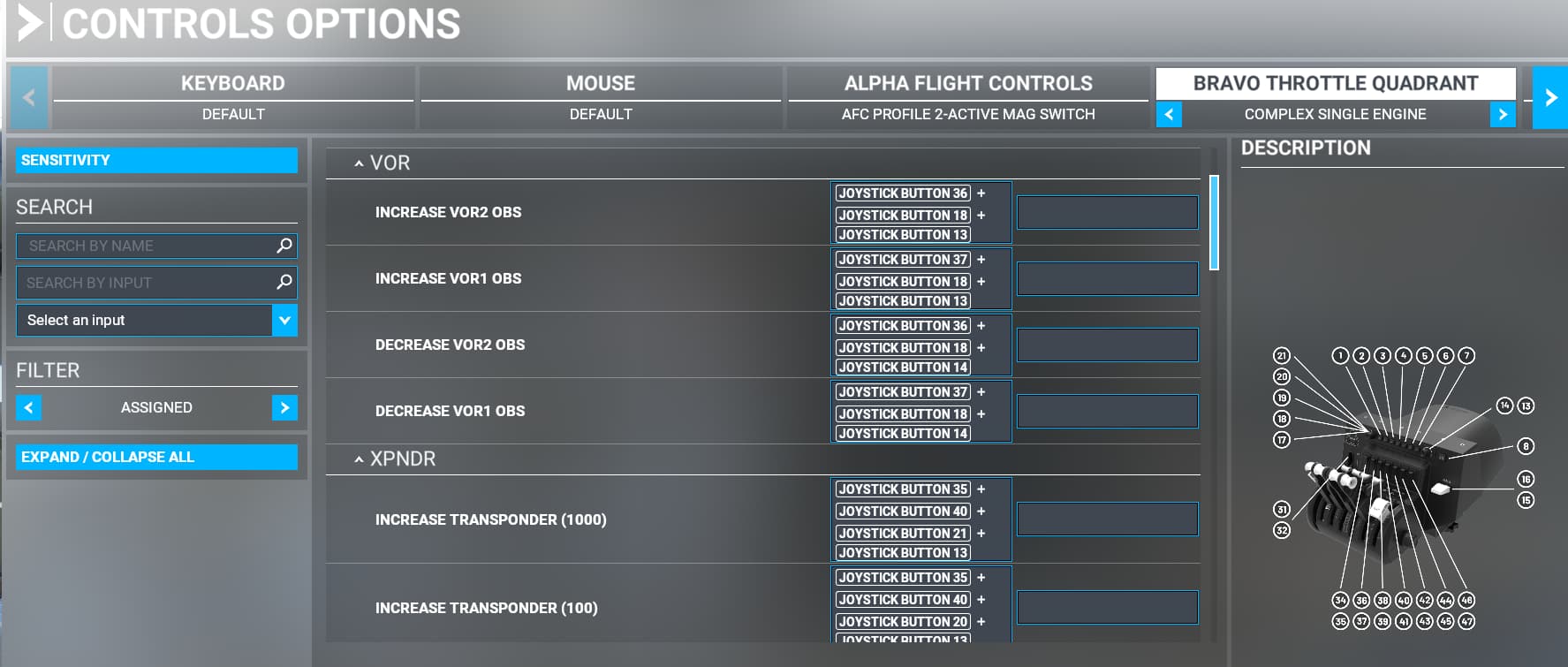
NAV Radios
NAV Radios
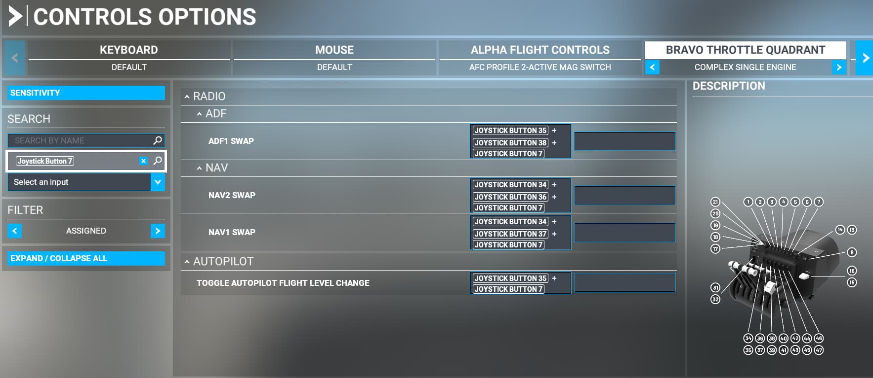
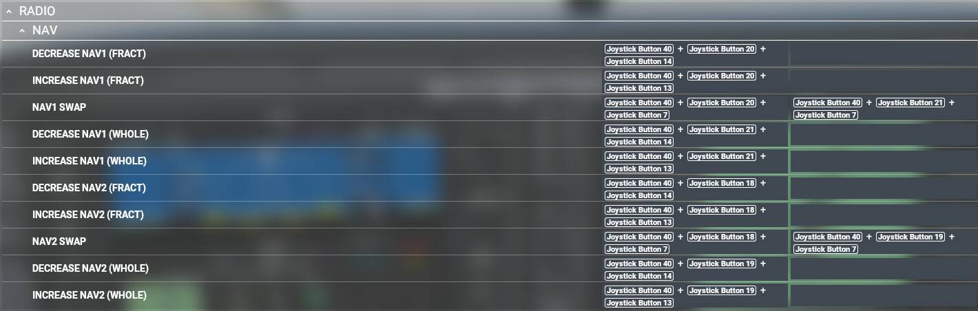
NAV Radio mode is selected by setting Button 40 (switch 4). Rest is similar to COMs.
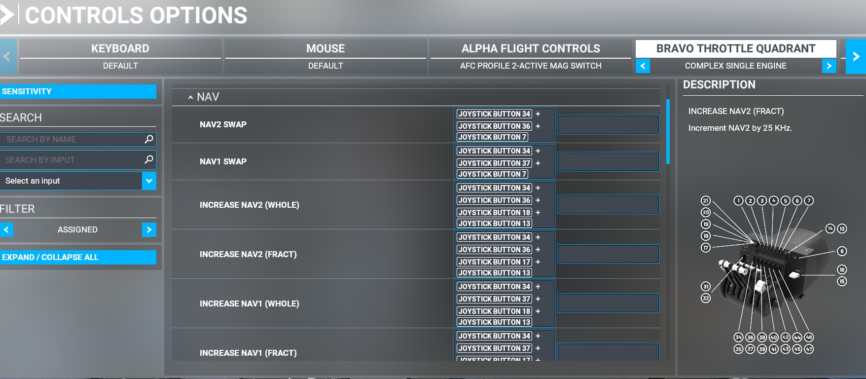
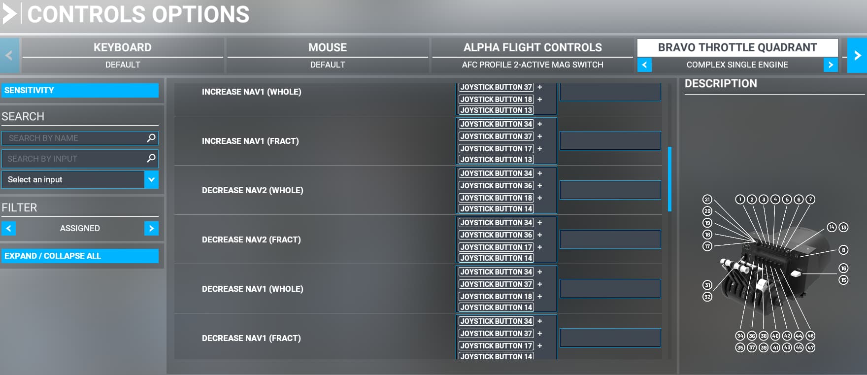
NAV1 function is selected by positions ALT (whole) and VS (fractional) on the left Knob.
NAV2 function is selected by positions HDG (whole) and CRS (fractional) on the left Knob.
Increment/Decrement is with the right Knob as usual.
Swap standby ⇄ active with IAS button. NAV1/2 depends on the position of the left Knob.
I have tested this setup with the following:
G1000: C172
G3000: TBM930
GNS530/GNS430: C172 Classic
Non-garmin: C152 (except mic selection)
Please note that I have set this up according to my needs. I’ve mapped the functions I feel I use the most and the way it makes intuitive sense to me. E.g., using the IAS button for frequency swap as that is right next to the adjustment knob; or keeping the COM1/2 and Altimeter selection in the same mode since I might me tuned to tower on COM1, listening to ATIS on COM2 and setting the altimeter after that.
Hope this helps! Feel free to tweak it according to your needs and post below if you have any similar setups!