Tool to connect Serial USB devices to MSFS2020 via SimConnect/WASM using VS2022

Chapter 4: Connecting with Arduino

On GitHub, you will find an example Arduino sketch. This sketch is based on the below connection diagram which is meant for a MEGA 2560 R3:

The example is meant for the FlyByWire A32NX. As the labels on the drawing already indicate, the demo controls the following:

  • EFIS_L CSTR (button to control + LED to show if active)
  • EFIS_L WPT (button to control + LED to show if active)
  • 3 digits of 7-Segment display (based on MAX7219) to show the HDG
  • Rotary Encoder to INC/DEC the HDG

Below I will explain step by step how to run the example, and what is happening behind the scenes.

1. Start the sim

Launch MSFS2020. Make sure that “Developer mode” is enabled (From main menu, select Options/General Options/Developers and set Developer Mode ON). Select a flight with the FlyByWire A32NX (this is a free add-on that needs to be installed separately) and select the start of a runway as Departure. Once the plane is started with the engines running, press “CTRL-2” to show the Glareshield/FCU. You should get a view like below.

Use menu “Window/Console” to show the console window that will give some more info about the WASM module. Best is to filter “habi_wasm”, which will only show the messages generated by my own WASM module. If you have copied the WASM folder from GitHub in the MSFS Community folder, then the WASM module should start automatically, which will be shown in the Console window.

Remark: Version in screenshot could differ from the pre-built one on GitHub. If you rebuild the source code of the complete VS2022 solution, you should have the latest version.

2. Connect with Arduino

First power the Arduino and connect it with USB. When powering up, the 7-segment displays will probably flash on for a fraction of a second, and then dim completely.

Launch the Cockpit Hardware HUB and enable the logging. Then press the Connect button. A lot of things are happening at once now.

  • The tool will first connect with MSFS2020 and start some processes to interact with SimConnect and WASM
  • Next the USB modules that are already connected will be detected, and the tool will attempt to communicate with them. It’s very common that Try 0 will fail with a TimeoutException, but Try 1 should be successful. The tool will do a maximum of 20 trials, which in case of multiple USB devices will all run asynchronously.
  • If a connection is established, the first command sent to the device is “IDENT”. The device will respond with a “DeviceName” and a “ProcessorType”. This is only informative, and is displayed in the “USB Device” field of the UI. In the screenshot this is “FCU A32NX” and “ARDUINO”.
  • The second command that is sent to the device is “REGISTER”. That tells the device to send all the “Variables” it requires to the tool, terminated by an empty string.
    In the Arduino sketch, I store the variables in a const char* array, which makes it easy to keep track of the number to be used later on - see below.
// variables (variables start at 001
const char *Variables[] = {
  "INT32_RW_L:A32NX_EFIS_L_OPTION,enum",                // 001
  "VOID_K:A32NX.FCU_HDG_INC",                           // 002
  "VOID_K:A32NX.FCU_HDG_DEC",                           // 003
  };
  • Once the variables are received by the tool, it will register them one by one. This is exactly the same as if you would do it manually by entering them one by one in the Command line, and press the button “>MSFS”.
    The result can be seen in the “Variables” window. You can also see the list of registered commands per Serial USB device on the left side of the UI.
  • During registration, the tool is going to send the current value of the variable back to the device. It does that by issuing the commands “[UniqueID]=[value]”. This is again the same as if you would enter this command manually in the Command line, and press the button “>Device”.
    The UniqueID is not the same as the number used in the device, which we call DeviceID. When a value from MSFS is sent to the device, the command “[UniqueID]=[value]” is translated in “[DeviceID]=[value]”. The opposite is also true, when the device sents a command “[DeviceID]=[value]”, the tool will translate it into “[UniqueID]=[value]” before processing towards MSFS.
    The “DeviceID” is the order in which the variables are sent for registration, starting from 1. This is the same order as the array in the Arduino sketch. Once the variable is registered, it gets a UniqueID that is used by the tool. Both are stored together with the registered variable.

3. Using the hardware

Now we can use the hardware. If you click on the CSTR pushbutton, and you would connect a serial port monitor on your Serial USB port, you would see the below:

image

First, the command “001=1” is sent from the device to the Cockpit Hardware HUB. 001 is the ID of the first variable in the Arduino. In the Cockpit Hardware HUB, this is translated in the “Unique ID”, which is 003. That’s why if you put the LogLevel on High, you will see the line:

image

This command is then processed by the tool and is being sent by SimConnect via the Client Data Area to the WASM module (because it’s an L-var) who will then translate it in a command being sent to the FlyByWire A32NX using a set_named_variable_value from the Gauge API.

If all goes well, the result should be that the CSTR indicator of the EFIS_L on the FCU should lit up. Because of the change in indicator status, the value change will be sent through the Client Data Area back to SimConnect and will trigger the UI to show the value 1 for that variable (because it is RW). This value change of the variable with UniqueID 003 will also be sent to the Device with command “003=1”. The tool is going to translate the UniqueID in the DeviceID, which means that the command “001=1” is sent on the Serial USB (which can be seen in the screenshot).

The Arduino will receive this command and the CSTR LED will lit up. The Arduino will also send back an Acknowledge to the tool, which is simply the character “A” followed by a newline. This to indicate that the command has successfully be received.

Remark: All commands sent from the tool to the Arduino are being acknowledged by the Arduino by sending back the sequence “A\n”. If an Acknowledge is not received within 150 msec, the command is sent a second time. If that fails again, the tool gives up and goes to the next command. The next command will only be sent to the device after an acknowledge is received. This way of working avoids that the commands from the tool are sent too fast.
There is no acknowledge protocol when commands are sent from the Arduino back to the tool. I have not implemented this, but this is not that dramatic. First, the Arduino will only send commands if you take some action (push a button, dial an encoder, etc…) which is not 100 times per second, so the tool will definitely be capable of catching up. Second, if it really would happen, then in this very exceptional case, you will notice that your action has no effect, and you will try again.

We can now also use the other button, and the Rotary Encoder. Below is a picture of the example at work.

image

4. Debugging your hardware

You can also debug your hardware without using the Cockpit Hardware HUB. You can use the “Serial Monitor” of the Arduino IDE, and enter the commands yourself to see the effect.

If you type “IDENT” followed by enter, you will see the below:
image

If you then type “REGISTER” followed by enter, you will see the list of variables that need to be registered:
image

If you now turn the Rotary Encoder UP or DOWN, you will see the commands “002=” or “003=” (These are UP and DOWN events, and don’t need a value).
image

If you type the command “001=1”, you will see the CSTR LED lit up, and you will also see that the device returns the sequence “A/n” which is the Acknowledge being sent back.

Goto Chapter 5: Example of using X-var

This is really cool. I use Mobiflight for all my stuff but would really like to learn coding. I made some modifications to some of the Mobiflight files in order to make a DIY FFB rudder pedal. The pedals work well, but I really don’t know what I’m doing. I’ve downloaded several FFB libraries and Simconnect tools, yet still don’t have clue.
I’m hoping to read through your posts and learn more about programming and using Simconnect. Thanks for all the time and effort you’ve put into this. I will be starting with your original tutorial before moving on to this one.

@JCSLOVE If you want to learn more about SimConnect, then I suggest that you first read my other post SimConnect + WASM combined project using VS2019 - SDK Discussion / Tutorials - Microsoft Flight Simulator Forums. There I try to explain all the basics first. The tool and source code provided here makes use of these basics.

I’m on chapter 2 and have just opened Visual Studio 2019 for the first time. So exciting…

Are VS2019 and VS Code interchangeable?

Chapter 5: Example of using X-var

This is an example of when you can make good use of the X-var in my tool. Let’s examine the below example variable definition to set the EFIS_L_OPTION:

INT32_W_X:s0 (L:A32NX_EFIS_L_OPTION, enum) == if{ 0 (>L:A32NX_EFIS_L_OPTION, enum) } els{ l0 (>L:A32NX_EFIS_L_OPTION, enum) }

You can use the same syntax for the EFIS_R_OPTION:

INT32_W_X:s0 (L:A32NX_EFIS_R_OPTION, enum) == if{ 0 (>L:A32NX_EFIS_R_OPTION, enum) } els{ l0 (>L:A32NX_EFIS_R_OPTION, enum) }

This will create variables which you can then use to set the EFIS_L_OPTION or EFIS_R_OPTION. Below screenshot shows both registered X-vars as variables 004 and 005.

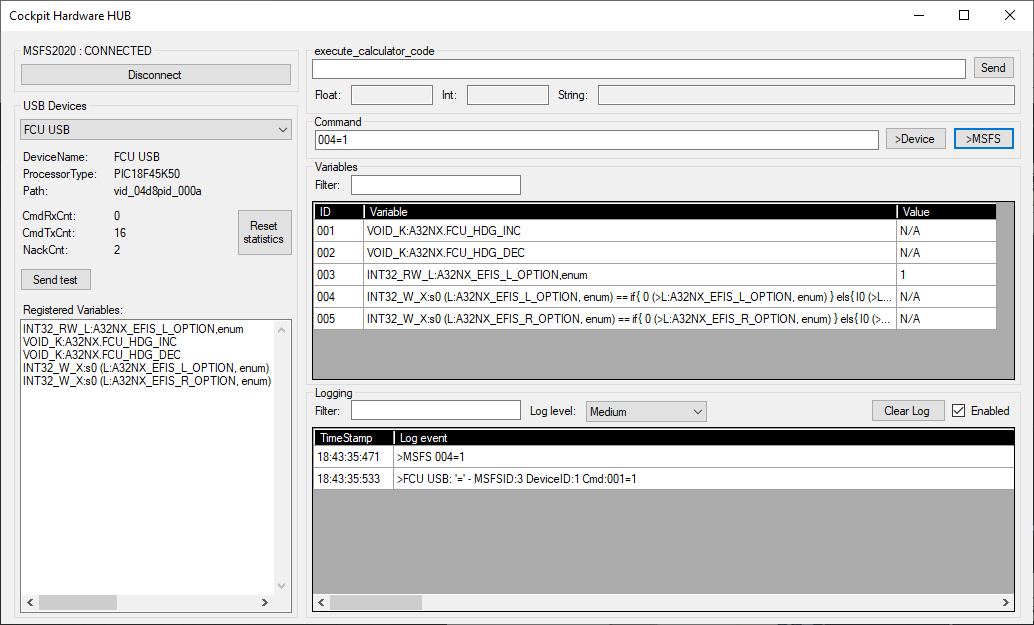
But why using this complex X-var, and not simply use the L-var that was already created in our previous example (see variable number 003):

INT32_RW_L:A32NX_EFIS_L_OPTION, enum

The reason is that for using command “003=[param]”, we first need to determine the parameter based on the current status of the EFIS_L_OPTION. This will require some coding in our device, and the result will be sending the command “003=1” or “003=0” (if we want to set/reset CSTR).

The advantage of using the X-var is that we I can now use the same command “004=1” in all cases. This will set or reset CSTR depending on the current value of CSTR. This makes it extremely easy to connect this with a simple button in your Hardware, which always will send “004=1” - no coding required. The same applies to setting/resetting the other EFIS_L_OPTION values WPT (004=3), VOR D (004=2), NDP (004=4) and ARPT (004=5).

X-vars make use of execute_calculator_code in the WASM module, and this makes use of strings written in RPN notation. Some basic knowledge of RPN is required to make use of the full potential that X-vars offer. Let’s dissect the command in more detail.

Let’s use the parameter 1 to set CSTR of EFIS_L_OPTION. In below explanation, “L-var” is just a shortcut for “L:A32NX_EFIS_L_OPTION, enum”. The string that is executed could look like below:

1 (L-var) == if{ 0 (>L-var) } els{ 1 (>L-var) }

  • 1 (L-var) ==
    This compares the value 1 with the value of the L-var. The result can be TRUE or FALSE. You can even try this in the “execute_calculator_code”, and depending on the value of your L-var, you will see 0 (false) or 1 (true) as return values.
  • if{ ... } els{ ... }
    If the previous statements resulted in TRUE, then the first { … } is executed. If FALSE, the second { … } is executed.
  • 0 (>L-var)
    This sets the L-var to 0 - this means that if CSTR was set, it will now be reset
  • 1 (>L-var)
    This sets the L-var to 1 - this means that if CSTR was not set, it will now be set

So basically, I’m checking if the current value of the L-var is equal to the required value (1). If it is, I reset it to 0. If it is not, then I force the value to the required value (1).

But the above only works for the value 1. If I want to use the value 2 (VOR D), I should use:

2 (L-var) == if{ 0 (>L-var) } els{ 2 (>L-var) }.

A more common approach would be to write this as follows:

param (L-var) == if{ 0 (>L-var) } els{ param (>L-var) }

We now have to find a way when I use the command “NNN=X”, the 2 occurrences of param in the string are replaced with X. But the problem is that when I give a parameter to our command, this is only going to be added in FRONT of the variable. We should find a way to store the param somewhere, and then re-use it later in the string.

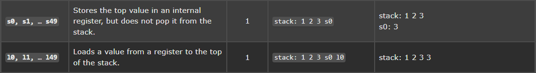
This can be done by using the RPN commands sN and lN. (be aware that the second command is the small caps “L”). Explanation of these commands can be found in the RPN documentation.

Now we can fully understand the string:

s0 (L:A32NX_EFIS_L_OPTION, enum) == if{ 0 (>L:A32NX_EFIS_L_OPTION, enum) } els{ l0 (>L:A32NX_EFIS_L_OPTION, enum) }

If we use the above with the command “NNN=4”, then in the WASM module, the following string is used with “execute_calculator_code” - the parameter 4 is added in front of the string:

4 s0 (L:A32NX_EFIS_L_OPTION, enum) == if{ 0 (>L:A32NX_EFIS_L_OPTION, enum) } els{ l0 (>L:A32NX_EFIS_L_OPTION, enum) }

First the 4 is stored in the internal register 0 using command s0. But the 4 stays on top of the stack, and is then used to be compared with the current value of EFIS_L_OPTION. If this is TRUE, then EFIS_L_OPTION is set to 0 (switch off). If this is FALSE, then first the stored param value is loaded from register 0 using command l0, which gives us the value 4, and then EFIS_L_OPTION is set to that value.

You can use the above string in the “execute_calculator_code” of the tool, and then change the 4 by a value between 0 and 5 and experiment with it. Below uses the value 2.

By the way, I haven’t invented this string myself. In my earlier post (see here), I showed a way how you use the “Behaviors” window to get some good examples of RPN strings. These are used by the developers of FlyByWire themselves. The above is exactly how they implemented the push-buttons of the EFIS_L_OPTION and EFIS_R_OPTION.

WARNING: Make sure you don’t exceed 256 bytes for the strings used to register variables.

Goto Chapter 6: Connecting with PIC Microcontroller

I have switched from VS2019 to VS2022 without any problem. If I remember well, you might just need to make sure that your target platform is set to x64, and you might have to enable both projects correctly (application and WASM), but for the rest, it seemed perfectly compatible. The complete transition, including downloading VS2022 and installing it, and then rebuilding my code after setting above correctly took me less than an hour.

I really suggest to switch to VS2022 as VS2019 is not supported any longer.

VS 2019 (and VS 2022) are the programs used to create and develop programs. VS Code is a text editor that is integrated to Microsoft programming languages and is mostly used to edit text files, if you don’t used the IDE (integrated Development Environment) GUI to edit your code in a project. ie. super developers that use the command line to compile. That is a simplistic explanation. So it’s up to you how you use or not use both.

Creating WASM projects is not really available for VS2022, there is no MSFS platform toolset available. Yes you can fudge it, but VS 2022 is 64 bit now (if you downloaded that version), so the 2019 toolset may or may not work correctly.

Thanks for your explanation. I was confused then - never used “VS Code” myself. I was only referring to VS2019 and VS2022.

All I can say is that I used my original VS2019 solution, and used in VS2022 without any issue. If I’m not mistaken, the new MSFS2020 SimConnect requires x64 target and doesn’t work for x32 anyway. Although, I do agree with you that different from VS2019, there seems not to be a specific “Microsoft Flight Simulator” platform when choosing C++ target code. By copying my earlier VS2019 code, all project settings seemed to be set correctly.

The SDK Documentation found here does indeed only mention VS2019. This means that if you ever going to build a WASM module from scratch, that some research might be required. Although, I have the feeling that the “standard C++ files” provided with the “Microsoft Flight Simulator” platform doesn’t give much specifics. I started them from scratch anyway. It might just be some specific settings for the compiler and linker that need some attention?

I’m not experienced enough to give correct advice here. So if other people can jump in, please do.

1 Like

Yes, that’s true for the WASM “server”. As far as I understand it, when you create a WASM project in VS2019, the template automatically creates links and references to the 64 bit SimConnect so you don’t even see it referenced specifically in the project.

However, you do not have to use a 64 bit SimConnect for the client to communicate with the WASM. In fact, Mobiflight uses a 32 bit SimConnect for its client and so do I in my own communicator, because I wrote it years ago, and didn’t want to go through all the hassle of rewriting all the other projects I have that depended on it, to x64

Chapter 6: Connecting with PIC Microcontroller

I like Arduino to make proto-types and do quick tryouts. But for the real work, my choice is the PIC microcontroller family from Microchip. There are a huge amount of different types, all having some specific hardware on board.

The one I’m using is the PIC18F45K50. One of the advantages of this type is that it has Crystal-less Full Speed (12 Mb/s) and Low-Speed Operation (1.5 Mb/s) USB on board. For prototyping, I’m using the 40-PIN PDIP package which can be easily put on a breadboard.

Software is developed using the MPLAB X IDE. You can download a free version, which doesn’t optimize the code, but which in my opinion is good enough for my cockpit hardware. I have invested in the MPLAB® PICkit™ 4 In-Circuit Debugger, which allows me to easily upload the code directly to the controller through an onboard programming interface (which implies that you give up 3 pins). But the additional advantage is that you also can do on chip debugging.

The MPLAB X IDE also offers a very powerful Microchip Code Configurator (MCC), which allows you to configure several features of the PIC microcontroller. This MCC generates the necessary code to use the USB, timers, interrupts, etc…

One of the main reasons I’m using the PIC microcontroller is that I only need 1 single chip with a few capacitors and I have a basic system. It’s as simple as that!

I quickly built the same configuration as I did with the Arduino in chapter 4. The difference is that in Arduino you can use C++, but in the free MPLAB X IDE I have to use C-language. But I don’t see this as a disadvantage, in the contrary. It gives me the feeling that I’m “closer to the hardware”, and have better control of the speed of my code.

The variables are stored in an array, and are sent to the Cockpit Hardware HUB when the “REGISTER” command is received.

const char *Variables[] = {
  "INT32_RW_L:A32NX_EFIS_L_OPTION,enum",                // 001
  "VOID_K:A32NX.FCU_HDG_INC",                           // 002
  "VOID_K:A32NX.FCU_HDG_DEC",                           // 003
  "INT32_W_X:s0 (L:A32NX_EFIS_L_OPTION, enum) == if{ 0 (>L:A32NX_EFIS_L_OPTION, enum) } els{ l0 (>L:A32NX_EFIS_L_OPTION, enum) }", // 004
  "INT32_W_X:s0 (L:A32NX_EFIS_R_OPTION, enum) == if{ 0 (>L:A32NX_EFIS_R_OPTION, enum) } els{ l0 (>L:A32NX_EFIS_R_OPTION, enum) }", // 005
  "INT32_R_L:A32NX_AUTOPILOT_HEADING_SELECTED,degrees", // 006
  };

The result can be seen in the below screen.

Be aware that the order of the variables in the device is not the same as the order in the Cockpit Hardware HUB. Example, the HDG_INC and HDG_DEC in the device are “002” and “003” (the DeviceID), but in the Cockpit Hardware HUB this is “001” and “002” (the MSFSID). The Cockpit Hardware HUB is doing the translation between DeviceID to MSFSID. Example, the command sent by the device to increase the heading is “001=”. The Cockpit Hardware HUB will translate this in “002=” which is sent to the SimConnect module. When the EFIS_L_CSTR is switched on, the SimConnect module in the Cockpit Hardware HUB will use the command “003=1”. This is translated in “001=1” when it is send to the device.

I connected the following hardware to the microcontroller (be aware that below commands are based on the DeviceID’s):

  • Rotary Encoder that will send the commands “002=” (CW) and “003=” (CCW)
  • 2 LED’s to show the EFIS_L_CSTR (“001=1”) and EFIS_L_WPT (“001=3”)
  • 2 push buttons to use the X-variables for the EFIS_L_CSTR (“004=1”) and EFIS_L_WPT (“004=3”)
  • MAX7219 based 7-segment display to show the HDG (“006=…”)

Although it is also included in the variable list, I’m not using the EFIS_R_OPTION in this demo.

I have built some definitions in the Microcontroller software that allows easy configuration of inputs (push buttons, encoders, …) and outputs (LEDs, 7-segment displays, …).

Example, for the encoders, I use the below structure:

typedef struct EncDef_t
{
//--To be initialized-----------------------------------------------------------
    uint8_t pinA;               // input pin connected with pin A
    uint8_t pinB;               // input pin connected with pin B
    const char* pCmdCW;         // command executed for CW
    const char* pCmdCCW;        // command executed for CCW
//--Internal variables----------------------------------------------------------
    uint8_t eState;             // current state of encoder
}; 

struct EncDef_t EncDefs[] =
{
//    pinA     PinB     pCmdCW                  pCmdCCW
    { pin_RB0, pin_RB1, CMD_HDG_INC,            CMD_HDG_DEC,             },
};
size_t nEncDefs = sizeof(EncDefs) / sizeof(struct EncDef_t);

Adding an encoder is simply done by adding a line in the array EncDefs[], which defines to which pins the encoder A and B pins are connected, and which commands are executed when the encoder turns CW or CCW.

When the controller software starts, an Initialize_EncCmds() is called that, based on the above definitions, configures the pins as inputs. In the main loop Process_EncCmds() is debouncing the pinA and pinB, and based on their states sends the CW or CCW command over USB.

The same principles are used for the buttons. A structure defines the pins and the commands executed (a command is defined when the button is pressed - another command can be defined when the button is released). The functions Initialize_KeyCmds() and Process_KeyCmds() do the rest.

I created some functions to put values on the 7-segment displays, where you can define the position and length. The implementation even supports chaining MAX7219’s. For the LED-outputs, I support direct LED’s but also using shift registers that can also be chained. The latter means that you only need a few pins to connect a large number of LEDs.

The result is below.

image

As you can see, the hardware is really minimal. Don’t be fooled by the add-on board on top, because this is only used to put power on the breadboard. I only use 3 small capacitors and one resistor to drive this microcontroller, including it’s USB interface that has a connector below at the right.

Currently the system is very responsive. Turning the encoder has immediate effect. I’m curious to see how the system will behave if I connect all the hardware of the A320 FCU to a single PIC microcontroller. I’ve done some experiments several years ago when I was still using the FMGS A320 on FSX. There I connected 4 encoders and a 2 x 8 digit display, including a lot of LEDs and switches, and the system still behaved very well.

I guess that this completes my software, which means that I now can continue on building my first A320 module which will be the FCU. The design is ready as you can see below. Wish me good luck! :slight_smile:

2 Likes

I noticed that the last post here was May 26th. Is this project still active?

I am a home sim builder currently using X-Plane 11. I have serious doubts about the future of X-Plane so I am hedging my bets.

My current sim is modeled after a Beechcraft 1900D and uses roughly 20 micro-controllers (Teensy 3.2 specifically, all driven by the TeensyDuino plugin for X-Plane)

I love this architecture because there’s no middleware. Just the plugin and the Teensys. I have looked at Mobiflight and while it is great for discrete I/O and steppers, it’s utility pretty much stops there.

The microcontrollers handle a myriad of functions. Mostly Discrete I/O but also driving real-world avionics. I have a pair of Garmin GMX-200 units that are driven by 1 teeny (Essentially just a moving map device tied to a Reality-XP Garmin 430 unit.

I have looked at a few MSFS2020 to Arduino programs but so far they are far from mature. I understand that the home cockpit world will require a few more years to catch up but I’m hoping to speed up that process. I’m a developer (SQL, C#, C++, some Python) and am about to retire at the ripe old age of 60.

…and I’m looking for a solid architecture to convert to from X-Plane without having to rewire/re-program my entire sim. I just want to upload some code for 2020 and go…

So, to that end…

  1. Is this project still active?
  2. Do you need/want help? :slight_smile:

ps: Here’s a recent pic of my sim:

1 Like

Hello @TheBeechHouse,

Wow, that picture looks impressive. I hope I can say the same of my simulator within 10… 15 years?

Although I didn’t post anything since quite some time, the project is definitely active. But “only” being 57, I still have a job, which doesn’t leave me “full time” to work on it.

The shortages on the chip-market didn’t help neither. I was ready to build the FCU with the PIC18F45K50 microcontroller, but that chip wasn’t available anywhere (or I had to wait until mid 2023). I took the decision to move to the PIC18F47J53. But then I had to deal with some changes first. The PIC18F47J53 used 3.3V, and my 7-segment digits based on the MAX7219CWG use 5V. I also couldn’t find my LED-drivers for the backlight any longer, so had to start searching the market again. At the end, I could find all my components, but to be sure I built another test-board first. On that test board I also learned how to solder SMD (using soldering station, but also used hot air for the first time). I also discovered that I didn’t have enough I/O, so played a bit with I2C I/O expanders as well. Etc, etc, etc…

But finally, I’m ready for the first build. My FCU PCB is on its way from JLCPCB (my regular stop for PCB manufacturing). I also ordered all my missing components, did some final adjustments on my self-made push pull encoders (added adjustment screws to precisely align the push and pull microswitches), and am now ready for the big build.

So that answers your first question: Yes, the project is active!

About your second question. Would you convert your X-Plane simulator to a MSFS simulator? That would be quite an interesting story (worth a long post :slight_smile:). But then you would rather need my help, instead me needing help from you. So I’m not so sure how to interpret your second question. Of course, your experience on the real build exceeds mine with a factor 1 to 100! Always good to know somebody that has already solved 1001 problems, and who is offering help. Really appreciated, thanks a lot! If I’m ever stuck…

I think it should be perfectly possible to control your hardware through the tool I developed. As long as your Teensy has a USB port through which you can receive and send commands (commands are textual, not even binary), then you are ok. I am now using the PIC18F47J53 microcontroller, but I have tested a lot of my software using Arduino. The main difference is that my MPLAB X IDE (the free of charge IDE used for PIC18F47J53 from Microchip Technology) uses C, and for Arduino I could use C++. Although, I used C in both developments to have some re-usability. I can share you my Arduino source code if you want, and if you need some explanation, I can share some insights as well.

The biggest challenge will be to find the correct commands in MSFS. I am using the FBW A32NX, which is of course different then Beechcraft 1900D. And I don’t know if MSFS has this type of plane available (I could only find Beechcraft type 18). If I’m not mistaken, PMDG had (or has?) a Beechcraft 1900D add-on.

A good starting point to get an idea of the commands is using the SDK documentation that you can find here. And if you haven’t done so, I suggest you read my tutorial mentioned at the beginning of this post. It will give some insights in how my tool fits together. Or maybe you know all this already, and you are the real expert here :laughing:

Once you have the commands, with your programming skills, it should be a piece of cake to gradually convert all your modules. Although, be aware that I have never tested my own tool on a large-scale project. I’m still a bit in the dark regarding performance, and I anticipate that I might need to tweak things in the future when I’m developing my own hardware. Regarding speed, with my PIC microcontroller I can easily run at about 300 commands per second (and the main limitation is the main loop cycling speed - one command per main loop cycle). On Arduino, with comparable complexity, I “only” reached 240 commands per second. Although, these numbers are still very premature. I hope to come with some better benchmarks when my FCU is finished.

Looks like we have quite some things in common. We have about the same age, we both seem to have knowledge of the same languages (I learned Python, but never really used it, but I “speak” fluently C, C++ and C# - and I am familiar with SQL) and we both have knowledge about microcontrollers and other hardware stuff. If you want to stay in touch, no problem! You can also PM me, and give me your email address, which might be easier when exchanging stuff. Up to you.

Marvelous piece of information you had shared! My gratitude for you to share your expert knowledge on the coding. I am currently doing a similar project and man MSFS does cause a headache for developers (Compared to X Plane which are way more developer friendlier). I really suggest Asobo should housekeep the API…

BTW, I don’t think the engines will quit if you turn all fuel pumps off, they will just be gravity fed (Unless your fuel is not deaerated, in which case it may cause vapour locking the fuel line, but then I don’t think FBW has that deep level of simulation) :wink:

2 Likes

Hello Mr. Billiet.
I have problems with USB/Serial connections and your Cockpit Hardware HUB.
I’ve tried many boards like mega 2560 ‘big’ version, mega 2560 mini version and some arduino nano with CH340 USB TTL converter.
Only the ‘BIG’ version of mega 2560 seems to work with the software (i have also tried with different baudrate in the HUB, also 9600) but same problem.
What’s the problem? Simple, the other boards weren’t recognized during the initialization process and nothing appened when i click ‘Connect’.
The board are named different in arduino Sketch but only the normal version of “Elegoo Mega 2560” was recognized and register the vars.

Can you have a clue of what is going on?
Thanks,
Simone

Hello Simone,

Please call me Hans, no need to call me ‘Mr.’ :slight_smile:

Are you using the second version of my CockpitHardwareHUB (see CockpitHardwareHUB_v2). This is a completely rewritten version, and is more robust than the first version. It also includes a detailed user manual. It also has an easy way to send logging to a file, which can be interesting while trouble shooting.

I assume that MSFS 2020 was running for your connection, because that is required.

Honestly, I only have the ‘BIG’ mega myself, so I haven’t tested it with different types. But there should be no reason that it doesn’t work.

Please try with the new version, set ‘Log level’ to ‘info’, and log to a file. You can send me the file via a private message (I assume that is possible?). I am interested in investigating this, because there was another person that sent me some improvement suggestion that has to do with detecting USB devices. If your logging doesn’t provide any results, I might just implement this little change, and we could try if this helps.

Hans

FYI, broken link.

Correction
flybywiresim/aircraft · GitHub

Hi Hans!
Thanks for this fast reply!
I haven’t founded the way to send private message, so i will post here.

I’ve downloaded the v2 but this time is getting worse, i think.
With the same board (and the stock arduino firmware that you provided with HUB v1) that worked with version v1, this time no life of usb connection in the software.
Also the Connect/Disconnect button doesn’t change when connected to SimConnect (via the log box).

I attach the log file (info level):

21/01/2024 20:24:21: Logfile created
-------------------------------------------------
20:24:25:758[0000] - Info - APP - SimClient.SetLogLevel: LogLevel set to Info
20:24:43:315[9999] - Info - CLT - Initializing WASimClient v1.2.0.1 for client 000007AD with net config ID -1
20:24:43:319[0004] - Info - APP - Simclient.ClientStatusHandler: Client event SimConnecting: "Simulator Connecting" - Client status: Initializing
20:24:43:360[0041] - Info - APP - Simclient.ClientStatusHandler: Client event SimConnected: "Simulator Connected" - Client status: SimConnected
20:24:44:366[1005] - Warning - CLT - Server did not respond to ping after 1000ms
20:24:44:367[0001] - Error - APP - SimClient.Connect: Server did not respond to ping, quitting.
20:24:44:370[0003] - Info - APP - Simclient.ClientStatusHandler: Client event SimDisconnecting: "Simulator Disconnecting" - Client status: 18
20:24:44:490[0119] - Info - APP - Simclient.ClientStatusHandler: Client event SimDisconnected: "Simulator Disconnected" - Client status: Idle
20:24:44:491[0000] - Info - CLT - Shutdown complete, network disconnected.
20:24:43:349[-999] - Info - CLT - Connected to Simulator "KittyHawk" v11.0.282174.999, with SimConnect v11.0.62651.3 (Server v5)

Screenshot of MSFS2020 A32NX in execution with v2 software opened.

Hope you can understand what’s going on.

Really appreciate your work!

Thanks,
Simone