Chapter 6: Connecting with PIC Microcontroller
I like Arduino to make proto-types and do quick tryouts. But for the real work, my choice is the PIC microcontroller family from Microchip. There are a huge amount of different types, all having some specific hardware on board.
The one I’m using is the PIC18F45K50. One of the advantages of this type is that it has Crystal-less Full Speed (12 Mb/s) and Low-Speed Operation (1.5 Mb/s) USB on board. For prototyping, I’m using the 40-PIN PDIP package which can be easily put on a breadboard.
Software is developed using the MPLAB X IDE. You can download a free version, which doesn’t optimize the code, but which in my opinion is good enough for my cockpit hardware. I have invested in the MPLAB® PICkit™ 4 In-Circuit Debugger, which allows me to easily upload the code directly to the controller through an onboard programming interface (which implies that you give up 3 pins). But the additional advantage is that you also can do on chip debugging.
The MPLAB X IDE also offers a very powerful Microchip Code Configurator (MCC), which allows you to configure several features of the PIC microcontroller. This MCC generates the necessary code to use the USB, timers, interrupts, etc…
One of the main reasons I’m using the PIC microcontroller is that I only need 1 single chip with a few capacitors and I have a basic system. It’s as simple as that!
I quickly built the same configuration as I did with the Arduino in chapter 4. The difference is that in Arduino you can use C++, but in the free MPLAB X IDE I have to use C-language. But I don’t see this as a disadvantage, in the contrary. It gives me the feeling that I’m “closer to the hardware”, and have better control of the speed of my code.
The variables are stored in an array, and are sent to the Cockpit Hardware HUB when the “REGISTER” command is received.
const char *Variables[] = {
  "INT32_RW_L:A32NX_EFIS_L_OPTION,enum",                // 001
  "VOID_K:A32NX.FCU_HDG_INC",                           // 002
  "VOID_K:A32NX.FCU_HDG_DEC",                           // 003
  "INT32_W_X:s0 (L:A32NX_EFIS_L_OPTION, enum) == if{ 0 (>L:A32NX_EFIS_L_OPTION, enum) } els{ l0 (>L:A32NX_EFIS_L_OPTION, enum) }", // 004
  "INT32_W_X:s0 (L:A32NX_EFIS_R_OPTION, enum) == if{ 0 (>L:A32NX_EFIS_R_OPTION, enum) } els{ l0 (>L:A32NX_EFIS_R_OPTION, enum) }", // 005
  "INT32_R_L:A32NX_AUTOPILOT_HEADING_SELECTED,degrees", // 006
  };
The result can be seen in the below screen.
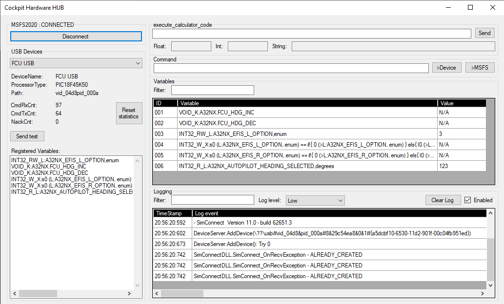
Be aware that the order of the variables in the device is not the same as the order in the Cockpit Hardware HUB. Example, the HDG_INC and HDG_DEC in the device are “002” and “003” (the DeviceID), but in the Cockpit Hardware HUB this is “001” and “002” (the MSFSID). The Cockpit Hardware HUB is doing the translation between DeviceID to MSFSID. Example, the command sent by the device to increase the heading is “001=”. The Cockpit Hardware HUB will translate this in “002=” which is sent to the SimConnect module. When the EFIS_L_CSTR is switched on, the SimConnect module in the Cockpit Hardware HUB will use the command “003=1”. This is translated in “001=1” when it is send to the device.
I connected the following hardware to the microcontroller (be aware that below commands are based on the DeviceID’s):
- Rotary Encoder that will send the commands “002=” (CW) and “003=” (CCW)
- 2 LED’s to show the EFIS_L_CSTR (“001=1”) and EFIS_L_WPT (“001=3”)
- 2 push buttons to use the X-variables for the EFIS_L_CSTR (“004=1”) and EFIS_L_WPT (“004=3”)
- MAX7219 based 7-segment display to show the HDG (“006=…”)
Although it is also included in the variable list, I’m not using the EFIS_R_OPTION in this demo.
I have built some definitions in the Microcontroller software that allows easy configuration of inputs (push buttons, encoders, …) and outputs (LEDs, 7-segment displays, …).
Example, for the encoders, I use the below structure:
typedef struct EncDef_t
{
//--To be initialized-----------------------------------------------------------
    uint8_t pinA;               // input pin connected with pin A
    uint8_t pinB;               // input pin connected with pin B
    const char* pCmdCW;         // command executed for CW
    const char* pCmdCCW;        // command executed for CCW
//--Internal variables----------------------------------------------------------
    uint8_t eState;             // current state of encoder
};

struct EncDef_t EncDefs[] =
{
//    pinA     PinB     pCmdCW                  pCmdCCW
    { pin_RB0, pin_RB1, CMD_HDG_INC,            CMD_HDG_DEC,             },
};
size_t nEncDefs = sizeof(EncDefs) / sizeof(struct EncDef_t);
Adding an encoder is simply done by adding a line in the array EncDefs, which defines to which pins the encoder A and B pins are connected, and which commands are executed when the encoder turns CW or CCW.
When the controller software starts, an Initialize_EncCmds() is called that, based on the above definitions, configures the pins as inputs. In the main loop Process_EncCmds() is debouncing the pinA and pinB, and based on their states sends the CW or CCW command over USB.
The same principles are used for the buttons. A structure defines the pins and the commands executed (a command is defined when the button is pressed - another command can be defined when the button is released). The functions Initialize_KeyCmds() and Process_KeyCmds() do the rest.
I created some functions to put values on the 7-segment displays, where you can define the position and length. The implementation even supports chaining MAX7219’s. For the LED-outputs, I support direct LED’s but also using shift registers that can also be chained. The latter means that you only need a few pins to connect a large number of LEDs.
The result is below.

As you can see, the hardware is really minimal. Don’t be fooled by the add-on board on top, because this is only used to put power on the breadboard. I only use 3 small capacitors and one resistor to drive this microcontroller, including it’s USB interface that has a connector below at the right.
Currently the system is very responsive. Turning the encoder has immediate effect. I’m curious to see how the system will behave if I connect all the hardware of the A320 FCU to a single PIC microcontroller. I’ve done some experiments several years ago when I was still using the FMGS A320 on FSX. There I connected 4 encoders and a 2 x 8 digit display, including a lot of LEDs and switches, and the system still behaved very well.
I guess that this completes my software, which means that I now can continue on building my first A320 module which will be the FCU. The design is ready as you can see below. Wish me good luck! ![]()
