I have recently started to fly using vor navigation and I find it really great- especially triangulation from another vor station. I think this old way of flying is really overlooked- I have not quite grasped distance measuring but its great fun.
Enjoy it while it exists. Some countries aim to have the all phased out in the next 4 years!
In au we’ve been losing about 200 stations a year.
Asobo had better hurry up, and get that OBS mode functionality added in that case. ![]()
Funny thing is that 10 years ago this is how we learned to fly basic IFR, all steam gauges, only a very simple GPS or no GPS at all. All VOR / DME / ADF for navigation. Flying BRNAV routes using point-to-point navigation. Its not that long ago ![]() .
.
I meant what I said…
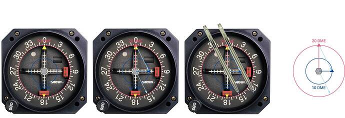
Here, this is how we were flying basic RNAV with just an OBI and DME, its called point-to-point. We used this during basic IFR training. Basically you draw imaginary circles and radials on an OBI in flight and then used a pen to shift the imaginary track between the two points to create a bearing, its really mickey-mouse navigation but what else can you do without a working GPS? We used to write down radials and distances from VORs to all airway points during pre-flight so we could fly directly to any one of them without using GPS.
You have to imagine the middle of the OBI is the VOR station, rotate the OBI so it centers with a FROM indication, the outer ring of the OBI is the higher DME and the lower DME is somewhere between the center and the outer ring.
For example:
From point A: radial 360, 20 DME
To point B: radial 090, 10 DME
Radial 360 is centered with a FROM indication, the outer ring is 20 DME. 10 DME is halfway between the center of the gauge and the outer ring, so you can now make two imaginary points. Now comes the fun part, you can use a pen (the thinner the better) or a toothpick or those tiny plastic sticks to stir the creamer in your coffee, whatever. Place it between the two imaginary points and slide it to the center, you can now read the track between the two waypoints (152 degrees).
And one picture without OBI for clarity.
And that’s all there is to navigate with just an OBI and DME, just make sure you read the track off the correct side, otherwise you’ll 180 degrees in the wrong direction ![]() . And make sure you center the OBI with a FROM indication and not a TO indication otherwise you’ll also go completely the wrong way. And if possible use a VOR which creates an angle close to 90 degrees between the two points, you can imagine that two points only 30 degrees apart from a particular VOR does not create an accurate bearing.
. And make sure you center the OBI with a FROM indication and not a TO indication otherwise you’ll also go completely the wrong way. And if possible use a VOR which creates an angle close to 90 degrees between the two points, you can imagine that two points only 30 degrees apart from a particular VOR does not create an accurate bearing.
That clicked! Thanks a lot.
This makes me happy! When you have mastered VORs don’t forget to give the ADF a try. Just like @ Nijntje91 said, in as little as 10 years ago we all learned this way and we did. I did my instrument training in real life in the late 90s and GPS was just a thing you heard about back then. One airplane in the rental fleet had it but it was not IFR approved and definitely no moving map.
And if you ever move into more advanced stuff like DME arcs etc. I posted this in another thread some time ago, maybe its of use here.
Regarding DME arcs, the official way is to make 10 degree steps from half scale to half scale. From full scale to center or center to full scale will result in a spiral inwards or outwards. You want to start on the arc, fly slightly in, pass abeam (CDI center) and then fly slightly out until back on the arc and then repeat. Hope that makes sense. You keep the heading 90 degrees to the CDI (no wind). RMI is indeed way easier, we didn’t have those on the aircraft I was instructing on.
You could also use the groundspeed indication based off the DME, I’m not sure if any MSFS aircraft had it though. Most conventional aircraft can give a groundspeed reading based on the DME rate of change, its only accurate flying directly towards or away from the station, during a DME arc it should stay zero as the rate of change is zero. Drawback using this technique is that if the groundspeed is showing something during the arc, you don’t know if you are flying towards or away from the station. Using the halfscale to halfscale technique you will see the groundspeed showing something, reduce to zero approaching abeam (CDI center) then increase until halfscale when making the next 10 degree heading change it reduces again. Its a nice tool to crosscheck using the CDI method. Again, no clue if any of the MSFS planes has it, maybe the steamgauge C172?
You can calculate the distance to intercept as follows: a 90 degree intercept will be 30 seconds when flying rate-one. 60 kts = 1nm/min, 120 = 2 and so on. So when flying at 120 kts, you have to start intercept around 1 nm out. Its not entirely accurate as you turn away from the beacon so its a little early normally but it gives some rough estimate and you can reduce bank when the DME decreases too slowly. You could do the same calculating when to leave the arc when there is no lead radial. Know that 1 degree at 60 nm equals 1nm. Since your example is a 20 nm arc, 1 degree will equal 0,3 nm, so again with 120 kts groundspeed you’ll need to leave the arc approximately 3 degrees (= 1nm) before in order not to overshoot the ILS.
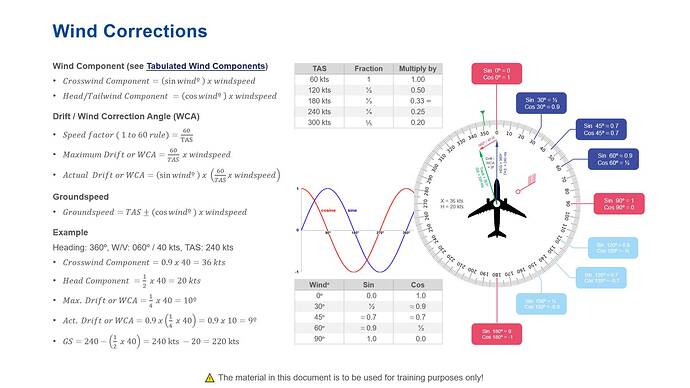
Its not an exact science so you don’t really have to calculate to the degree or 0.1 nm accurate, but some understanding and rules of thumb would help in giving some rough estimates. Eventually you won’t really need to calculate anything and roughly know when to turn taking into account ground speed. Same applies to wind corrections, it may seem very theoretical and only for the mathematical inclined amongst us, with some practice you will be able to estimate your wind correction needed. I did try to summarize wind corrections onto one page when I was an instructor:
Simply speaking you need to memorize the fraction depending on TAS, 60 = 1, 120 = 0.5 etc. (flying faster means the wind has less effect) multiply this by the windspeed and you know the maximum wind correction angle. Then you need to remember the sin of 30 degrees, 45 degrees and 60 degrees.
-
The first step involves calculating the maximum Wind Correction Angle (WCA), this is done by multiplying the before mentioned speed fraction by the windspeed. So if the wind speed is 20 kts and the TAS is 60 kts maximum WCA = 1 x 20 = 20 degrees, for 120 kts WCA = 0.5 x 20 = 10 degrees etc. You now know already 2 things, if the wind is directly from the nose or tail the WCA = 0 degrees, if the wind is directly cross the WCA = maximum (10 degrees in our example).
-
If the wind is from any other direction you’ll need to apply a correction for that, knowing that if the wind is 30 degrees from the nose or tail it will be 0.5 x maximum WCA, 45 degrees is 0.7 x WCA, 60 degrees = 0.9 x WCA. So in our example of 120 kts TAS and 20 kts windspeed:
-
Maximum WCA = 0.5 x windspeed = 10 degrees
-
0 degrees (head / tail wind) = 0 degrees WCA
-
30 degrees = 5 degrees WCA
-
45 degrees = 7 degrees WCA
-
60 degrees = 9 degrees WCA
-
90 degrees (crosswind) = 10 degrees WCA
Luckely thats all the mathematics involved for basic IFR flying, and most of it is just guess work anyway ![]() .
.
(Former Instrument Rating Instructor)
VOR navigation is a hoot. Anybody can hit the direct key and follow a magenta line. If you have any questions, ask away.
In the PA44 it’s so difficult to follow a course as the CDI deflection is 10 degrees minimum even with a single click of the mouse.
Personally I love VOR flying as it gives the brain a workout (relative to following the magenta line).
Just fired up the PA44 and the course and heading selectors give 1degree increments. I have the PMS50-GNS530 mod, however.
That’s not the plane. It’s almost certainly the bug where you have latching switches on your controls. It will affect all aircraft. Unbind the latching switches, and the problem should go away.
You must either have a Honeycomb yoke or another peripheral that has “always on” switches. That’s a known issue that causes the 10 degree bug. This issue should be fixed with the next sim update in the coming days.
I’ve unbound those switches on my Honeycomb (I have other switch panels) to get rid of the issue, but look forward to re-binding them for alternate functions once the fix is in place.
Thankyou Stateside
This is just great- thank you for posting.
Wellllllll we weren’t working with ADF ten years ago. ![]()
To you guys that correctly said that it’s a latching switch issue, thanks I have read about this but not overcome it just yet.
I have a Warthog throttle and stick but also I use my fanatec wheel and thrustmaster MFDs so a lot of buttons ![]()
Sorry to derail the excellent thread about VOR navigation but until I fix this it’s not really possible (unless I set a course then manually align with it and then engage autopilot)
Like I said in my post, they said in the Q&A that this should be fixed with the next patch, so you won’t have very long to wait.
This is not correct. It was decided that there would always be retained a minimum coverage of VORs so that in the event of an aircraft losing GPS they can safely navigate.
See for example the FAA’s “VOR MON” (minimum operational network):
EDIT: BTW Australia has definitely said they will retain ground-based system:

