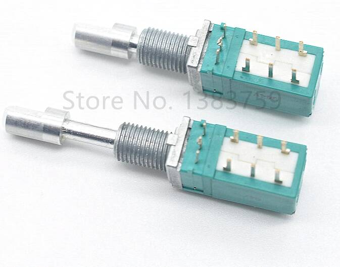
https://www.aliexpress.com/item/33052314061.html?spm=a2g0s.9042311.0.0.67954c4dgaxqIH
I can’t find any information about the pinout.
I assume maybe its a dual rotary encoder because there are 6 pins at the base and maybe push switch and a pull switch with the three pins at the top.
Anybody have any experience with these?
Thanks,
Chris
1 Like
Now I am thinking maybe the base 3 pins are A GND B and the bottom three pairs are for the double switch with the middle pin being the input and the top pin and bottom pin being shorted with the middle depending on whether the shaft is extended or retracted like a DPDT toggle. If that is correct, this would be ideal for an a320 AP button box. This would be more consistent with the description. I hope it is not a potentiometer.
The fact that the description talks about pulse points suggests it is an incremental encoder generating pulses as you turn it rather than a absolute encoder with a binary output for each position.
What sort of encoder were you actually after ?
I am looking for an encoder to use in an a320 autopilot panel. Just need to detect clockwise and counter clockwise turns and then pull switch for selected mode and push for managed( or the other way around?)
Chris
Thats not the type of encoder you want. The description is a bit misleading as the “push” and “pull” mechanism is there to push the encoder inside to lock it there and push it again out to be able to use it. It is not sending pulses pushing the encoder in or out. It just latches the encoder knob.
If you want to build a real push/pull mechanism, I would suggest to look for solutions on the internet.
I, for myself, have realized it with a second button and build a housing around the encoder to pseudo-pull the housing against the button.
Others have realized it in a way that you use just one button to toggle between the states. I made a video on how to realize both solutions software-wise with Mobiflight:
There was a deleted post earlier in the thread with a link to alps potentiometers.
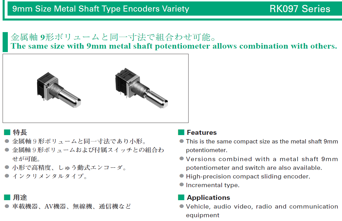
https://tech.alpsalpine.com/prod/e/pdf/potentiometer/rotarypotentiometers/rk097/rk097.pdf
Number 12 seems to have the same form as this encoder. The diagram notes the base pins are R1 meaning possibly resistor. Then the pair of 3 pins are labeled A C B and the diagram seems to indicate that A C disconnected and C B connected with the shaft in either pushed or pulled configuration. This is why I am partly thinking it’s a mislabeled potentiometer. But if it is truly an encoder with just a locking shaft, what would the pair of 3 pins be for?
But even if it is like that - How would you realize the push/pull function? IMHO the one or two button set-up makes more sense than the locking shaft.
If my hunch is correct, then this is a rotary encoder mated with a DPDT switch. Basically, you treat the bottom 3 pairs of terminals as the terminals of a DPDT toggle switch (A C B). Push the shaft in causes middle pins to short with the most bottom pins (C contacts B) and then pull the shaft causes the middle pins to short with the top pin (C contacts A). It said " double self-locking switch" so I hope that self-locking means latching. The double I hope means two switches which would make each 3 terminals on each side a switch. It would be easy to implement the push pull mechanic if this is the case. Connect an input pin pulled LOW to C and a 5v on B. (Expert arduino makers please correct me if I am wrong). Closing the contact between C and B will set C to HIGH which would be a detectable change in your sketch that you can use to set a boolean value. If both sides are insulated from each other, you can even wire an LED on the mirror terminals on the other side. Connect a 5v and LED and resistor on B’ and a GND on C’. This time a resistor is necessary because you don’t have a high impedance input pin in the circuit. So for the cost of one IO pin, you have push pull mechanic and a status LED. Its not even a problem if the shaft locks against rotation when pushed in because that is the “Managed Mode” setting in the AP, where the values you set with the encoder are overridden anyway by the Autopilot.
I had deleted the RK097 post because I saw to late, that it was a potentiometer and not a rotary encoder. I hope you will get an encoder and not a potentiometer. I only now as smallest type the 11mm Encoder from Alps and TTE, single and dual shaft. The only encoder I found with 9mm is here, but not in your construction:
https://tech.alpsalpine.com/prod/e/pdf/encoder/incremental/ec09e/ec09e.pdf.
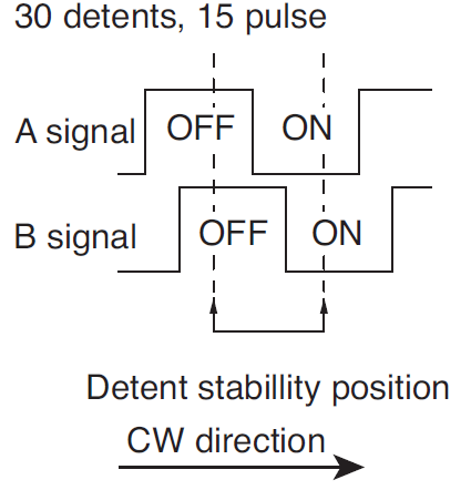
Usually, encoders have two outputs A and B that are offset by a certain rotational distance, C is GND. Either the latching takes place after a complete cycle, e.g. 20 detents with 20 pulses, or the latching takes place after both outputs have changed the edge. For example, 30 detents with 15 complete pulses. Depending on this, the software must be able to evaluate half or full pulses in order to correctly recognise the direction of rotation.
Do you know how I could test if its a potentiometer or an encoder with a multimeter?
I think if it is a potentiometer, I would see a linear rise in resistance between middle and first pin. But would that ruin it if it is an encoder? Hate to hook it up before knowing. Ordered it but haven’t arrived yet.
Chris
Hi Chris,
a potentiometer has no detents and as you say a rising resistance. If it is an encoder you have 20 … 30 detents per turn and you can turn endlessly. At one detent is a shotcut (near 0 ohm) between the middle contact (most pin C) and the and the outer pins A and B. At the next detent the contact is open.
Michael
Thanks a lot. I will post my findings when I receive the package.
Chris
I received the package today. It has detents and turns endlessly. I checked with a multimeter and the middle pin shorts with the outside pin in one position and open at the next detent. Also I checked the pairs of pins in the base. When the shaft is extended, the middle and top pins are shorted. With the shaft depressed (locked), the bottom pin is shorted with the middle. The left and right side are disconnected. The shaft does not lock against rotation when it is pushed in. So I think this is an encoder that would be perfect for push and pull action on an airbus AP module.
Airbus Engineer 1: Darn it! The Sim Community has finally figured out where we get our encoders from.  The one you can’t buy from Amazon.
Airbus Engineer 2: You mean, they won’t have to 3D print those housings with a toggle switch inside? 
Airbus Engineer 1: Wait till they figure out where we get our LED panels.
Chris
In my collection of data sheets of Alps I found one from 2002, there were encoders in the design RK097 and also the hint, that a feature with switch is possible. Uploading a PDF is not possible, here a screenshot.
Thanks for the research. This information is so obscure. I don’t think anybody has used this device for any projects.
Thanks,
Chris
Hi,
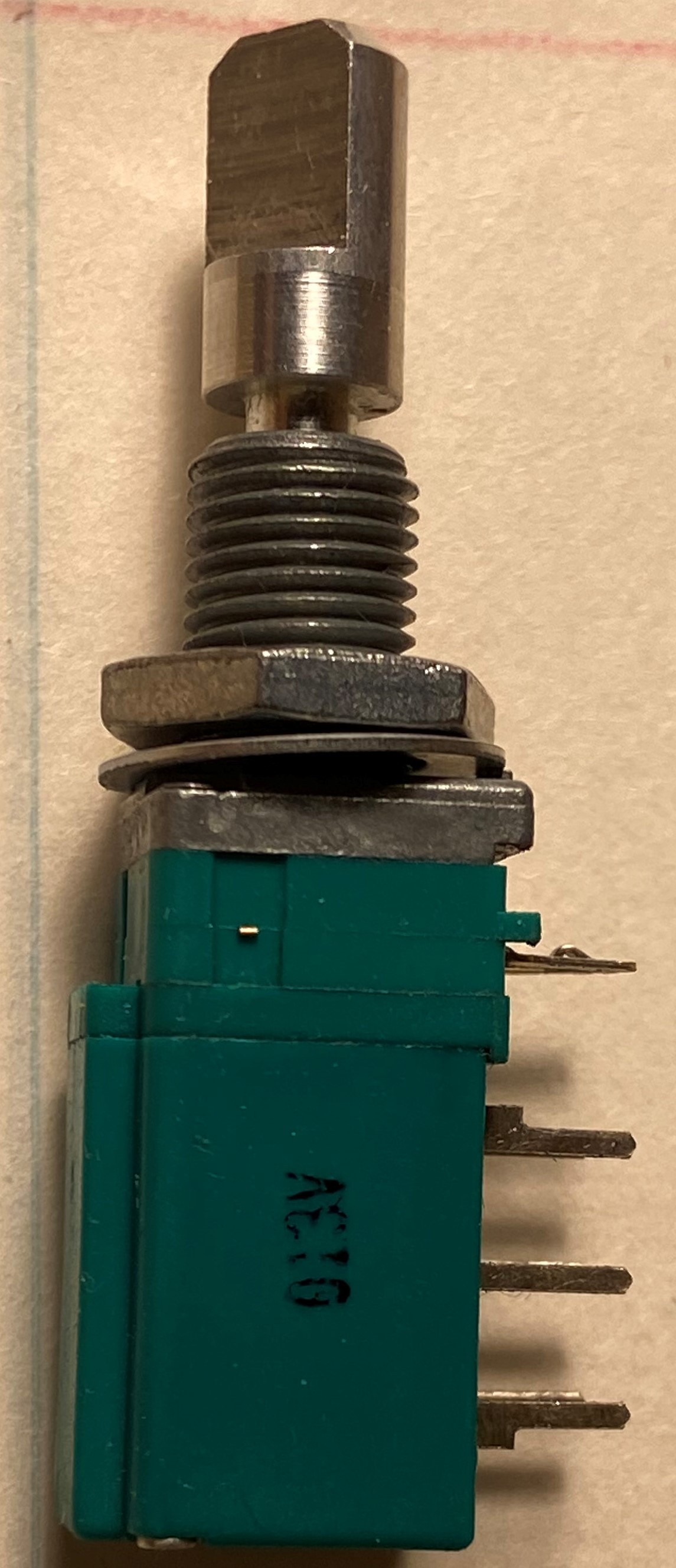
I tried to follow the link in your first post but it nows redirect to another page. Do you have any reference (maybe written on the encoders) so I can focus my search? I wasn’t able to find any even similar.
By the way, how are those working by now?
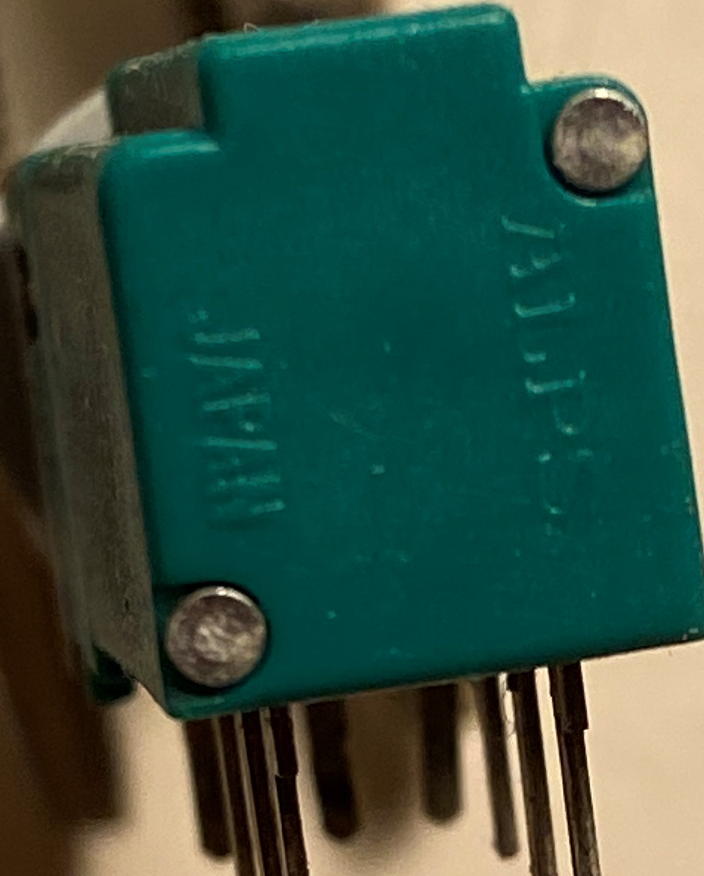
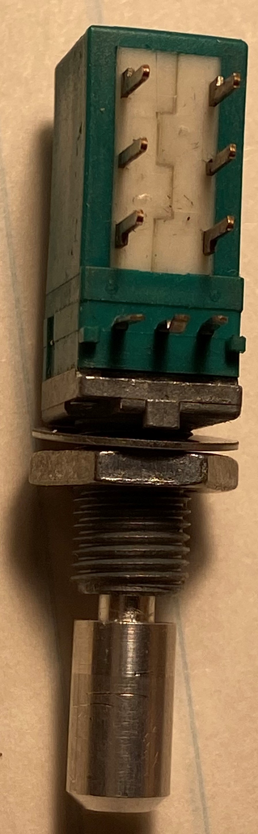
Here are some pictures of the encoders:
I really haven’t worked on my planned A320 panel because I can’t find a reasonably priced locally available faceplate. After I finnished my Cessna radio panel, I realized that I couldn’t make very good rectangular cutouts on plastic enclosures. Custom face plates saved the project. So my encoders sit in the workbench.
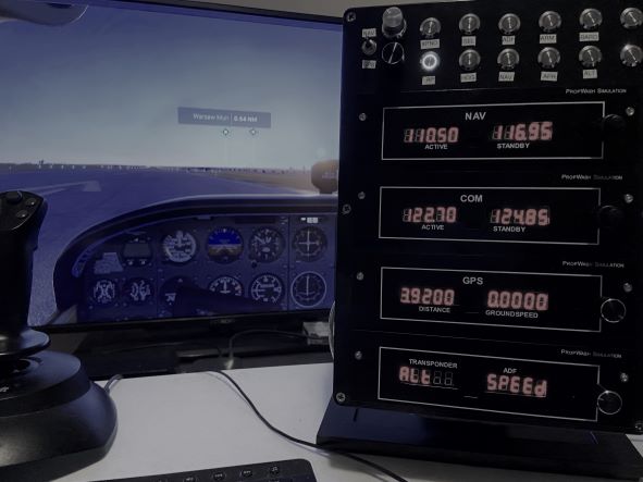
My Cessna Radio panel:
Cheers,
Chris