I have an Keyestudio pro micro to control it. The person that designed it including the code file with it..but I can’t get it to work. I get an error Joystick.h no such file or directory, so I used the joystick library from github. Now I get the same error message but for encoder.
I am completely computer illiterate so I really don’t know what I am doing. This is why I need some help from you knowledgeable folks.
It would be great if someone can quide me step by step on this. I want to set it up like any controller so that windows sees it as a controller, so I can use it for all aircraft in the sim, rather than do it through mobiflight, I am under the impression that for mobiflight you need to set it up for each aircraft separately.
You CAN set it up for each individual aircraft with Mobiflight but you don’t HAVE to. I have a button box that I use for everything. It’s nice to be able to make different profiles for different aircraft if need be. For instance, the 4 dual rotary can be used for a GNS530 and GNS430 in a 172 or as COM and NAV radios in a 152.
There are way too many excellent videos on YouTube for me to give justice to a written tutorial here. It took me less than a minute to program each function. Very simple.
I got it working, more or less. watched a youtube video.
some buttons still not working, calibration seems to be an issue as all the levers only show mid travel, acceleration is not smooth it jumps from mid power to full power. I also need to figure out the trim wheel.
I need you to indicate the pins you have used on the board for each axis, button or switch, and a description of their functionality. Have you followed the diagram that came attached with the files of the models to be printed?
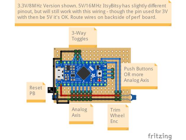
I will get them to you tonight. I did not use the same pins exactly. The hall sensors I used the TX and Rx pins. I did not install the capacitors cause I did not have a value, not sure if it matters or not.
here are the pins: throttle A3, Prop A2, Mixture A1, Top PB 7, front PB 6, Rear is reset, (left switch) Gear up 15, gear down 14, (right switch) flaps up 16, flaps down 10, hall sensors TX and RX pins. Flaps switch will probably be replaced with a momentary on switch (don’t know if this will change the code)