Introduction
The purpose behind the constant speed propeller system is to achieve a high propulsive efficiency over a wide speed range. A fixed pitch propeller is only efficient over a very small speed range. A fixed pitch propeller optimized for climb will have good performance during take-off and climb (low speed) but during cruise the blade angle is too low. A fixed pitch propeller optimized for cruise has good cruise performance (high speed), but during take-off the blade angle is too large so performance is lower, more runway required, slower climb rate etc. The constant speed propeller aims to be efficient over a wide speed range, if the correct speeds and power settings are used this will result in optimal blade angle for the phase of flight and optimal performance.
What you want to achieve is optimum power or optimum efficiency depending on the phase of flight.
Related topics:
- Basic propeller aerodynamics:
- Free-turbine turboprop engine:
Maximum Power
- Power = torque x RPM
In other words maximum power is achieved when running 100% torque (turboprop) or manifold pressure - MAP (piston engine) at 100% RPM. 100% torque / MAP at a lower RPM results in lower than rated power. So torque or MAP is not a direct measurement of power, its an element. When running at 100% torque and 100% RPM the engine is producing its rated power (Turboprop: Shaft Horse Power - SHP, piston: Brake Horse Power - BHP ) which is published in the POH. For turboprops, the engine itself is also producing a bit of jet thrust as not all the energy is extracted from the exhaust flow and converted into mechanical energy so the total power output is usually 10% higher than stated.
In short, for take-off, and maybe also for climb you want maximum power = max torque x max. RPM.
Best Economy
For all other phases of flight you are likely looking for the best economy over maximum power, which means the lowest fuel burn per unit of thrust. A propeller is basically an airfoil and similar to a wing the best lift / drag ratio is reached between 2 to 4 degrees angle of attack on the propeller. The angle of attack on a propeller is depending on:
- RPM
- TAS
- Blade angle
If all three are in balance then angle of attack (in cruise for example) will be around 2 - 4 degrees on the propeller. RPM is obviously selected with the RPM lever and automatically maintained by the propeller governor. Blade angle is (indirectly) selected by the power lever. When adding power the propeller tends to spool up, the propeller governor increases the blade angle to maintain RPM. The TAS is what is resulting from the thrust produced and aircraft drag. If all three are in balance the angle of attack is optimal.
In the POH performance chapter there might be several combinations of power versus RPM settings to be used for cruise. It all depends if you prefer speed or economy, the higher power / RPM combinations result in a higher TAS but would also burn more fuel while the lower power / RPM combinations would result in a lower TAS but also a lower fuel flow. Remember the following:
- Power = torque x RPM
So maximum torque / MAP x maximum RPM will be highest power = highest TAS = highest fuel burn, vice versa for lower power settings.
Constant Speed Propeller System
Diagram:
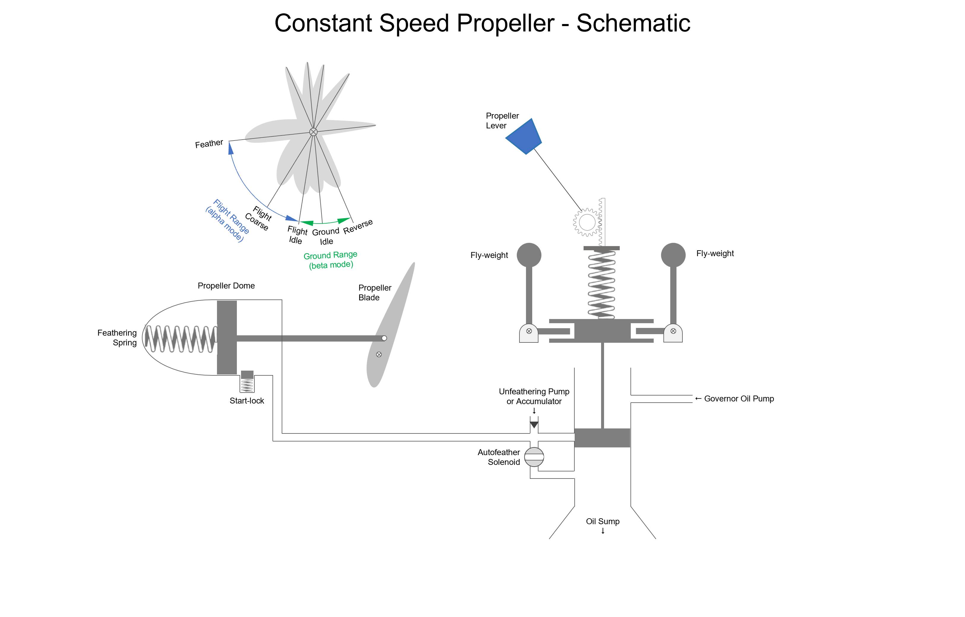
Components:
- Constant Speed Unit (CSU) consists of a valve which modulates oil pressure to and from the propeller dome, this valve is controlled up and down by the balancing act between a spring which is controlled by the propeller lever and two fly weights. Important to understand that those fly-weights are turning around with the engine, they are mounted on top of two “L-shaped” brackets and are able to pivot at the corner of the “L”, thus are able to move the valve up / down. The tension of the spring which holds the fly-weights down is adjusted by the propeller lever.
- Oil pressure is supplied by a governor oil pump, the hydraulic medium used is engine oil, the same oil used for lubrication of the engine. The oil is usually supplied to the propeller dome via an oil channel in the crankshaft, I tried to keep my schematics as simple as possible so I took some short cuts.
- A feather solenoid (if auto feather installed) is a valve which is opened (automatically) in case of an engine failure to dump oil pressure and feather the propeller without the need for placing the propeller lever into the feather position. Its not shown on the diagram but placing the propeller lever into the feather position mechanically lifts the valve in the CSU up, essentially bypassing the whole spring and fly-weight system.
- To unfeather the engine after the engine has been feathered oil pressure is needed. On a free-turbine engine you can simply start-up the engine with the propeller feathered and unfeather as soon as oil pressure is available. On any other type of engine you need to unfeather the propeller in order to start, this is done with an electrical unfeathering pump or a unfeather accumulator which stores oil pressure when the engine is running. The oil pressure is released from the accumulator when moving the propeller lever out of the feather position.
- The propeller dome houses a feathering spring which pushes on a piston which is mechanically connected to the propeller blades, placing them into the feather position. On the other side of the piston oil pressure is used to press the piston against the feathering springs into fine, and eventually ground idle and reverse positions (if applicable). There is a whole system installed which let the power lever directly control the blade angle when in the beta / ground mode by modulating the oil pressure, but that is for another time maybe.
- On free turbine engines it doesn’t matter if the propellers are feathered after engine shutdown on ground, on any other type of engine the engine can’t be started with the propeller feathered. Therefore one or more start-locks are installed. The start lock consists of a spring pushing the lock inside the dome to prevent the piston from moving all the way to feather, locking the propeller into a fine position. Centrifugal force flings the lock out when the engine is running, removing the start-lock.
Single engine versus multi-engine
On single engine piston aircraft the propeller system is built so that oil pressure keeps the propeller into a coarse position, whenever oil pressure is lost the propeller moves to full fine so the propeller will “windmill”. On a single engine aircraft the priority is to keep the engine running to perform a restart.
On a multi engine aircraft the priority is to remove the drag and continue flight on the remaining engine, therefore the propeller system is designed to go to the feathered position whenever oil pressure is lost, oil pressure is used to keep the propeller in fine pitch in flight.
Also on free-turbine engines you don’t want to have the propeller windmilling as it only creates drag and doesn’t turn the engine itself for a restart. The TBM and C208 for example feather when oil pressure is lost.
All the diagrams below are for a multi-engine / free-turbine engine aircraft (oil pressure = fine pitch, lack of oil pressure = coarse pitch and eventually feather). For single engine aircraft the principles remain the same but its working opposite (oil pressure is coarse pitch, lack of oil pressure is fine pitch).
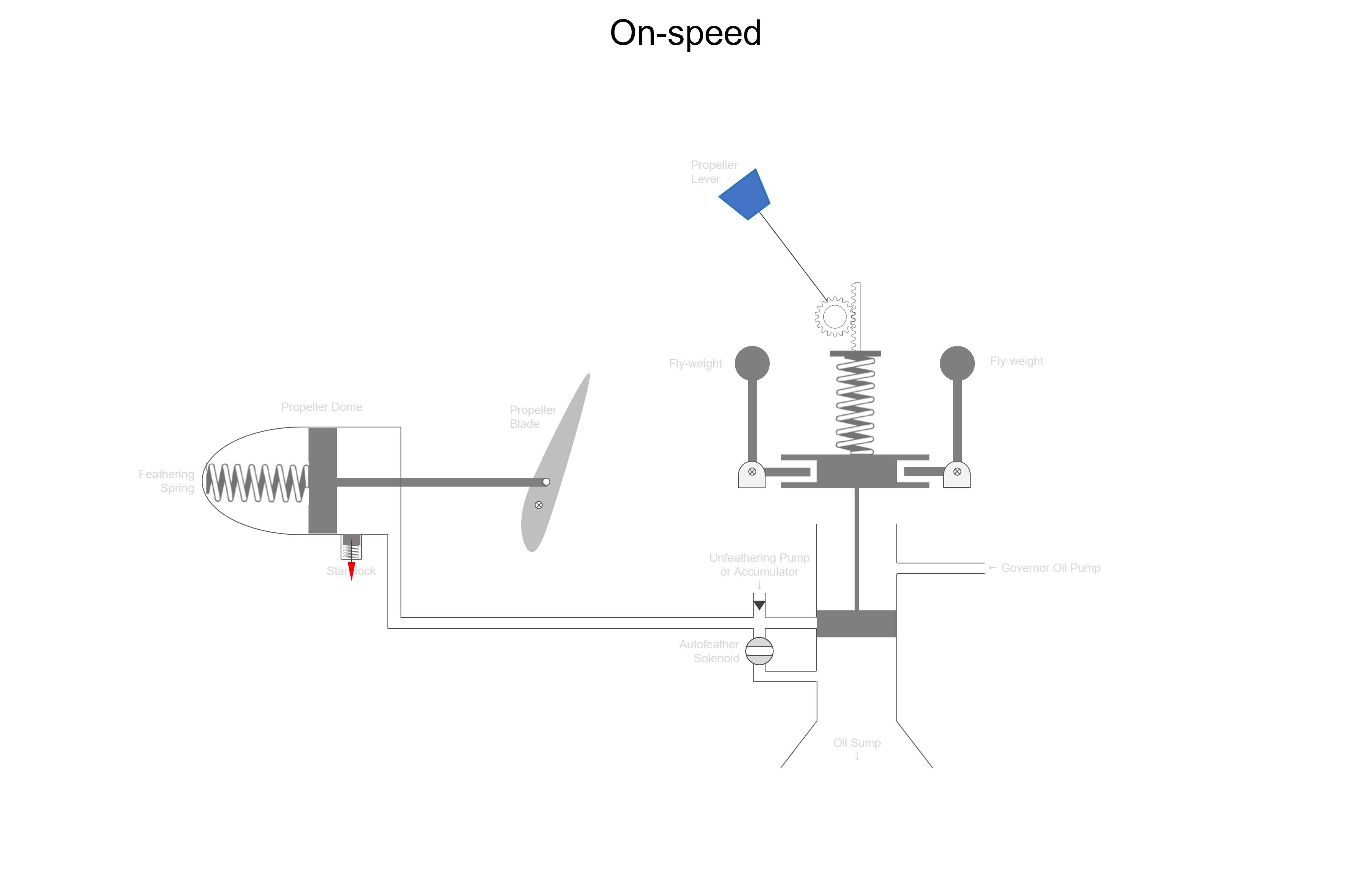
On-speed
Below the on-speed condition. The propeller is running at the selected speed, the piston blocks oil from going into, or moving out of the propeller dome, creating a “hydraulic lock”.
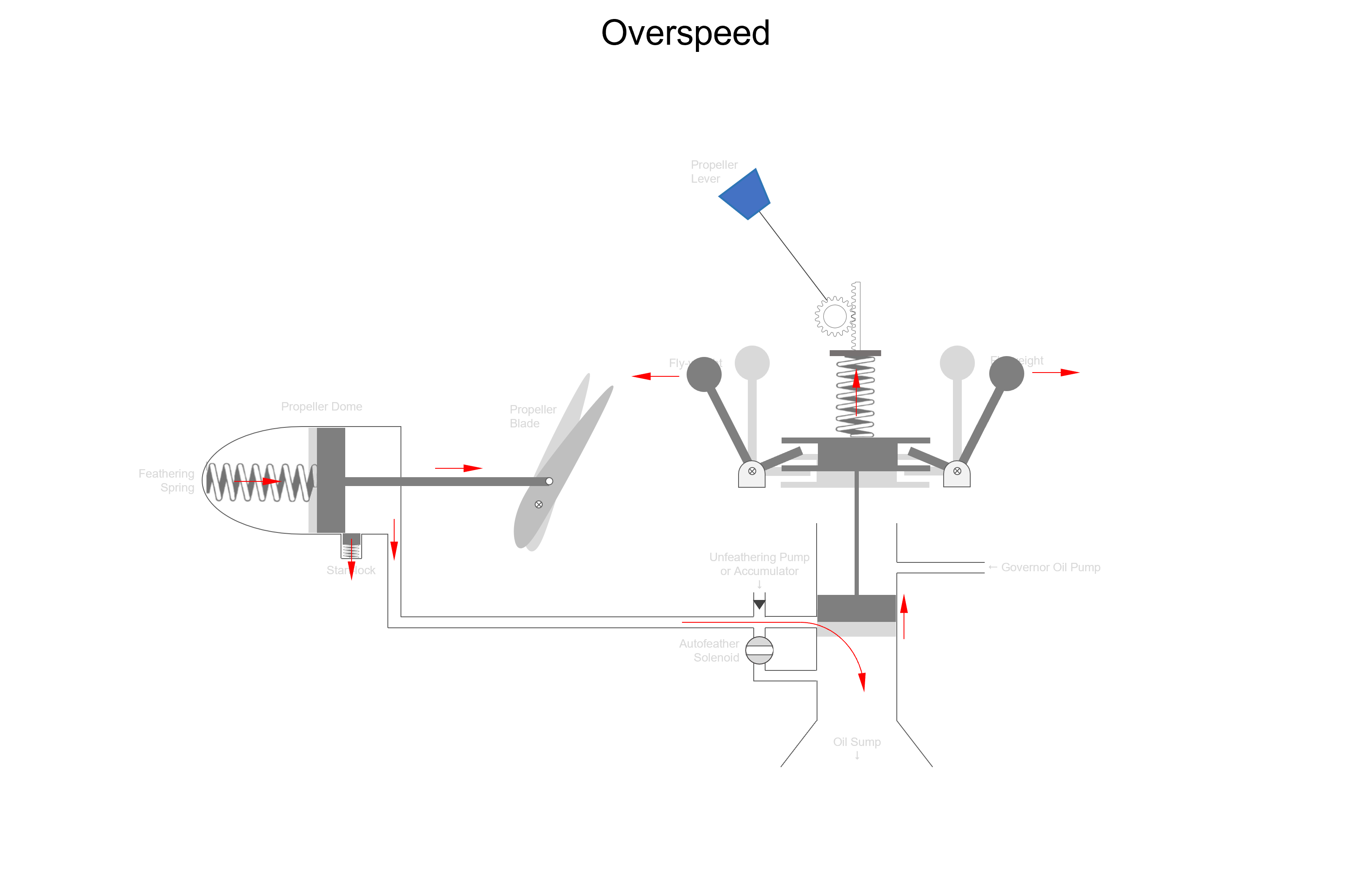
Overspeed
When the propeller is rotating faster than the selected RPM the fly-weights are flung out by centrifugal force and pull the piston up to dump oil pressure from the propeller dome. As oil pressure in the propeller dome decreases, the feathering springs push the propeller into coarse pitch. Coarse pitch means the propeller takes a larger bite of air, producing more thrust, also creating more load on the engine. The propeller RPM drops back to the selected RPM and we are back “on-speed” as in the first picture.
Examples of when this happens:
- Adding power (moving power lever forward)
- Increasing speed, for example starting a descent without reducing power
- Selecting a lower RPM (moving RPM lever back)
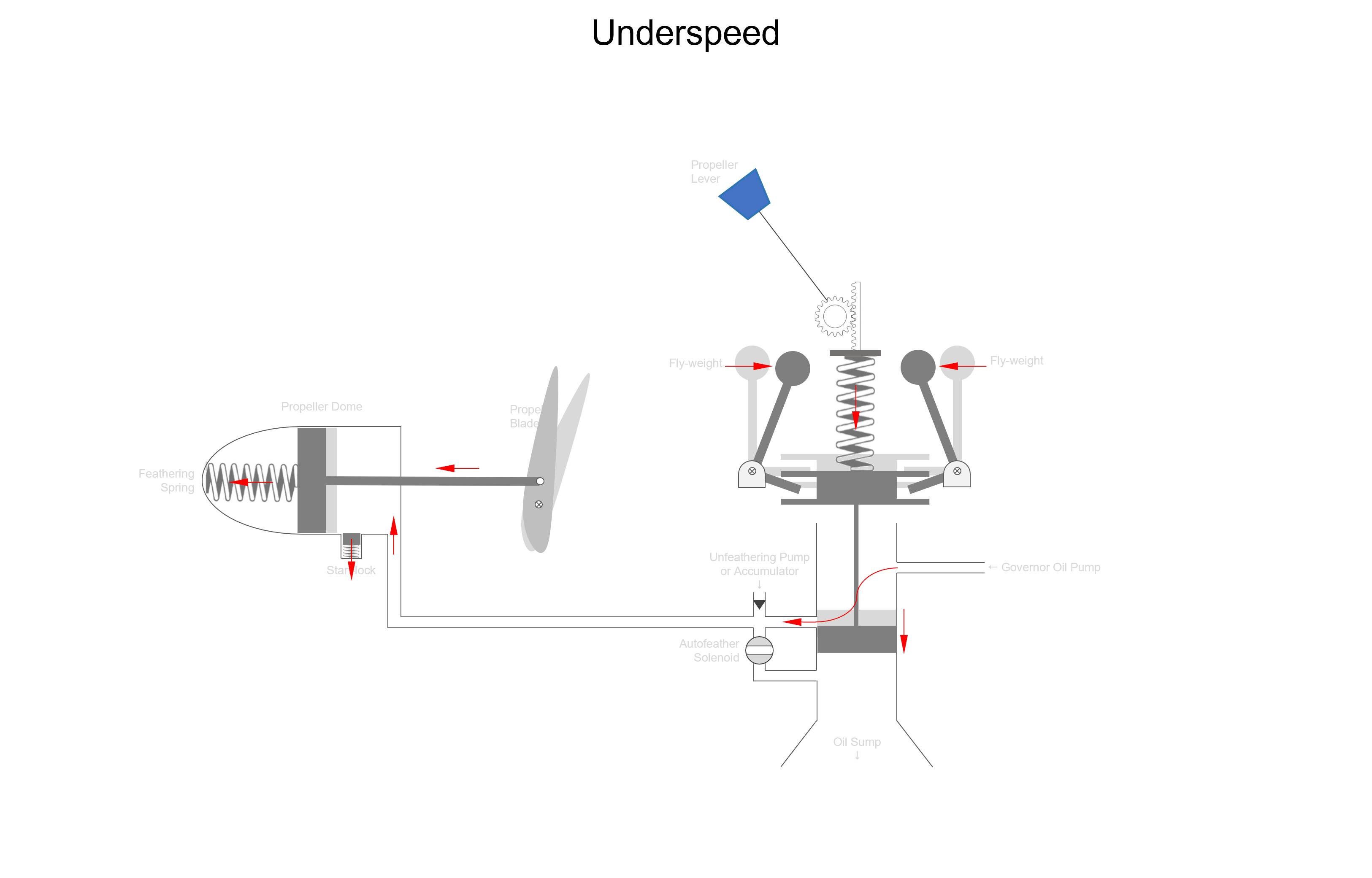
Underspeed
When the propeller is rotating slower than the selected RPM, the spring is able to push the valve down against the fly-weights due to the lack of centrifugal force. Oil from the governor pump can now enter the propeller dome and move the piston in the propeller dome against the feathering springs to the left, placing the propeller blades into fine pitch. Fine pitch means the propeller is taking a smaller bite of air, thrust reduces and load on the engine reduces. The engine RPM spools back up to the selected value and we return to an “on-speed” condition as in picture one.
Examples of when this happens:
- Reducing power (moving power lever back)
- Reducing speed, for example starting a climb without adding power
- Selecting a higher RPM (moving RPM lever forward)
Engine failure
As explained before, when oil pressure is lost a multi-engine / free turbine propeller system, the propeller will feather. This might sound like the propeller will automatically feather upon an engine failure, this is not true! As the engine fails, RPM drops and this is sensed as an underspeed by the propeller governor, consequently the propeller is brought into fine pitch. In fine pitch the engine will windmill and as long as the engine windmills the governor pump is running, as long as the governor pump is running there is oil pressure available to hold the propeller in fine pitch. So you either need an autofeather system which automatically feathers the propeller or otherwise manually pull the propeller lever into the feathering range to dump oil pressure and bring the propeller to a stop.