Readers please note that since posting the following, my project has moved in a very different direction. The biggest change is that I’ve abandoned pulleys and timing belts in favor of chains and sprockets, in order to handle the much greater torque that was delivered by the Banebots 13:1 gearbox, which replaced the 4:1 gearbox in the project described below. Unfortunately, since making this change of direction I’ve run into a variety of [real-world, not sim-related] complications that have together prevented me from completing the new version. I still plan to do so, but at this moment [January 19, 023] I cannot offer a firm target date for getting there. Please keep this in mind when reading the following post, especially if you’re considering building a similar model.
Original post:
I’ve put together what might reasonably be described as a hybrid of VR FlightSim’s two versions of a force feedback yoke. Like his Version 1, my design relies on the control mechanism used in the MS Sidewinder 2 FFB joystick, as well as using the motors from the Sidewinder 2. Other aspects of the design are based on Version 2, including reliance on Banebots gearboxes to magnify the torque of the motors; a frame made of v-slot aluminum extrusions; purchased metal pulleys; and wide (15mm) timing belts. This post provides a summary of the device, along with links to detailed instructions on building it.
Having previously built Version 1 and been somewhat disappointed at the result (sluggish action, plus a strong tendency for the narrow timing belts to slip, requiring constant adjustment), I was delighted to see VR FlightSim’s video and related photos for a “Version 2” FFB yoke. The new design seemed likely to address the major problems I had encountered with Version 1. Eventually, I decided that if I wanted a finished yoke, rather than one that was permanently “in progress,” I would have to do some work of my own.
This post reports on the finished project – as finished as it’s going to get in my hands, anyway.
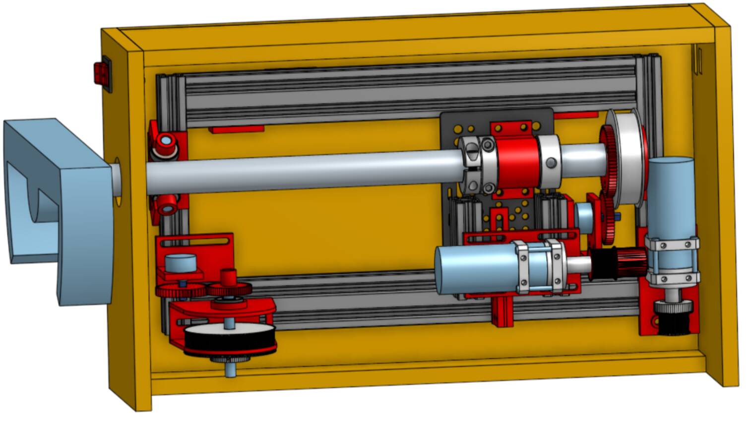
In addition to the components mentioned above, my case remains based on v1 – partly because I didn’t know where to buy the elegant panels shown for v2, and also because I did not see where the electronics would fit into that elegant case. I therefore stuck with the v1 case – and indeed opted for a thicker type of MDF, ½” (or roughly 12mm). Of course, this makes the final product heavier, but that was not a serious constraint for me. The three photos below show the finished project.
In any case, the “hybrid” yoke works, to my satisfaction at least (see video below). The feedback forces created are far greater than with my version 1, and the action is much smoother. (The feedback forces could easily be increased further, simply by replacing the 4:1 Banebots gearboxes used here with versions with a higher gear ratio.) Travel along the pitch axis is 145mm, not too far short of the Cessna 172’s 160mm; the roll axis ranges -/+90 degrees, just as in the C172. In case anyone would like to use this design or further refine it, I’ve provided links at the end of this post to detailed instructions, STL files for the printed parts, and a list of materials. Meanwhile, the remaining text below provides some general discussion of design tradeoffs and related issues. I will be happy to answer any questions, but please note that my bandwidth is limited by a disability.
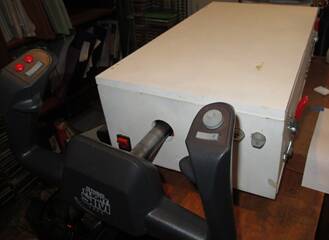
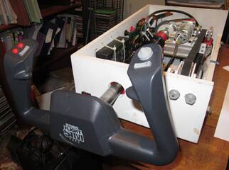
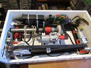
You’ll notice from the photos above that the yoke handle is taken from my old CH Products Flight Sim Yoke, which provides a lot of conveniently placed buttons that I didn’t want to lose. Using the CH yoke handle requires harvesting the appropriate printed circuit board from the latter, which I hot-melt glued to the case wall. I extended the many wires from the yoke handle by soldering them to a set of telephone wires, which run down the yoke column and exit through a hole drilled in that column. This is all straightforward for those who have this yoke and want to sacrifice it this way – just don’t cut any wires unless you need to. Otherwise, to save space I’ll move on to the main project. The figure below should be familiar to anyone who has watched the video of Version 2 – the main difference being that the figure shows the two potentiometers that keep track of the position of the yoke in the pitch and roll axes. Readers who find the summary below puzzling should refer back to this figure.
The frame starts with two 2040 extrusions running in the y- or “pitch” direction (closer and farther away from the pilot), each with its end holes tapped for a pair of M5-0.8x25mm screws; I used 350mm extrusions, but in hindsight wish that I had used 400mm extrusions instead. That’s because the length of the motor plus gearbox limits the travel of the yoke to around 145mm (5.7 inches), whereas the actual travel of the Cessna 172 yoke is around 160mm (6.3 inches). It might be possible to squeeze the extra 15mm out of the current frame, but lengthening the frame by 50mm would make it much, much easier.
Doing so would simply require lengthening the case, the steel tube attached to the yoke handle, and one of the two timing belts, plus replacing one of the two gears on the pitch axis with one with more or fewer teeth.
The 2040 extrusions are attached to 200mm long 2020 extrusions running in the x-direction, with 5.3mm holes drilled 10mm and 30mm from each end, and countersunk to accommodate M5x25mm socket head screws. This arrangement seems quite rigid.
The pulley, motor, and potentiometer controlling roll movements ride on the gantry cart shown in the photos on the VR FlightSim site – the OpenBuilds V-Slot Gantry Kit Universal, which features a gantry plate 122mm x 88mm and ball-bearing rubber wheels. This size exactly fits between the 2040 extrusions when fastened to 200mm-long cross members as described above.
I wanted to provide clearance for the gantry cart wheels and to be able to run wires under the frame, so I lifted the frame up on four “20x40 connectors,” each 5mm high. These 3-D printed connectors are used for other purposes in this design, including as endstops for the gantry cart and to connect 2020 extrusions together – see below.
The CH Products yoke uses a 1-inch shaft, so I based the design on that measurement. Those who supply their own yoke handles might do better to use a 20mm steel tube, which is easier to find matching parts for, notably the 72-tooth pulley connected to its end: pulleys like this with a 20mm bore are easy to find on Ebay, while it is difficult or impossible to find similar pulleys with a 1-inch bore (on Ebay, that is). Having decided to use a 1-inch tube, I ordered a pulley with a 20mm bore and then drilled the hole a bit larger to fit on the tube, using a 1” bit.
The far end of the yoke column assembly consists of a 3D-printed socket and plug (similar to those used in v1), the 72-tooth roll pulley just mentioned, and a 60-tooth gear designed on OpenScad. These three pieces are bolted together to ensure rigidity.
The second cluster of attachments to the steel tube consists of a 1-inch ID needle bearing housed in a 3D-printed bracket that is screwed to the gantry plate. On either side of the needle bearing/bracket assembly, I placed a needle thrust bearing with washers, and finally a shaft collar secured to the shaft to keep everything in place. At the far end, a single collar is used; at the end closer to the handle, I used two two-piece shaft collars that do double duty: first to keep the shaft aligned in the y-direction, and secondly to limit rotation of the shaft to realistic angles as well as to protect the connected potentiometer from physical damage. They do this by carrying a screw inserted into a hole drilled and tapped into the collar body (I used ¼” bolts because I had extras and the necessary tap; M6 screws would work just as well.) With the screws in place, the collars are then adjusted so that one screw hits the left-hand extrusion when the yoke handle reaches the maximum counter-clockwise angle desired, while the other screw similarly limits rotation in the clockwise direction when it hits the extrusion on the gantry plate.
Although most of the design relies on metric hardware, the two Banebots gearboxes suggested in the outline of v2 do not: they must be mounted using 10/32 hardware, and have a 1/2-inch diameter output shaft. To mount the gearboxes, I designed and printed a bracket for each, with holes for 10/32 x ½-inch screws (and M5 washers) going upward into the gearbox and slots for M5 screws to secure the bracket to an aluminum extrusion, using M5 sliding T-nuts. In the case of the roll motor carried on the gantry cart, the motor mounting bracket is secured to the top of an 80mm length of 2040 extrusion, secured at the bottom to the gantry cart, again with M5 screws and M5 sliding T-nuts. This arrangement allows the pulley on the output shaft to be adjusted in two dimensions.
Between the two extrusions, a 3D-printed belt clamp is secured to the gantry cart, projecting out over the right-hand extrusion. This clamp can be adjusted to take up slack in the pitch timing belt and to align with the pulleys at either end of the case.
The penultimate element riding on the gantry cart is a 3D-printed bracket to carry the potentiometer that detects movement in the “roll” direction. Placing this bracket on the extrusion allows the potentiometer to be adjusted easily so that the yolk handle is upright when the “roll” potentiometer value shown in DIView reads 50%.
Finally, we have the 24-tooth pulley mounted on the ½-inch keyed shaft of the Banebots gearbox. After searching in vain for a manufactured pulley of this type, I gave up and printed one of my own. This pulley is linked to the 72-tooth pulley on the yoke column via a 15-mm wide timing belt.
By comparison, the “pitch” side of the design is simple. The gearbox and motor sit on a mounting bracket on top of one end of the frame, with a 24-tooth manufactured pulley with a 12mm bore drilled out to 1/2 -inch (12.7mm). At the other end of the frame is a second pulley, this one with 72 teeth and clamped to an 8mm stainless steel rod, which itself turns in a pair of 608zz roller skate bearings mounted in a 3-D printed bracket. The end of that rod holds a 40-tooth printed gear, which in turn mates with a 61-tooth gear attached to the “pitch” potentiometer. When the yoke handle is pressed into or pulled away from the housing, the “pitch” potentiometer turns, sending a signal to the electronics to turn on the motor and exert force in the opposite direction.
The final piece of the design is the bracket that carries the weight of the yoke column shaft at the near end of the case. This bracket features two 608zz bearings mounted on short lengths of 8mm steel rod, each set at a 45-degree angle to the horizontal; the shaft rides on top of these bearings. This arrangement provides smooth movement in the y-direction, and minimal resistance to turning the shaft from side to side. The only problem with this bracket is its height – if you follow my design at every step of the way, you may have good luck using the fixed bracket I’ve attached below. Otherwise, you might consider the two-piece adjustable version of the bracket more flexible.
Finally, note that rather than rely on the power supply from the MS Sidewinder 2 Force-Feedback joystick, I used instead a 24-volt DC power supply purchased on amazon.com. This allowed me to reduce the number of exposed high-current wires, and to use a grounded plug rather than the old-style non-polarized plug included with the Sidewinder. In my design, a computer-style power cord is inserted into the matching receptacle mounted on the case. The “hot” and “common” terminals of the plug are connected to the lighted switch at the front of the case. When that switch is turned on, power flows to the power supply, and from there to the holes in the printed circuit board labeled “red” and “black.”
Finally, let me offer a few minor observations about this design.
First, please DO NOT follow the advice in the version 1 directions to remove the metal shield from each of the motors. These shields play an important role in the operation of the motors: without them, the motors generate significantly less torque.
Second, although the case is fairly roomy, it can be difficult to reach some of the screws with hex wrenches if and when adjustments are needed. After much agonizing, I eventually drilled a number of small holes in the case to allow me to reach those screws more easily.
Third, after experiencing similar frustration trying to secure the frame to the case using screws and t-nuts, I eventually resorted to running zip-ties around members of the frame, and passing those through holes drilled in the case.
The total cost of this design is around $350, not counting the Sidewinder joystick or the yoke handle. The Banebots gearboxes account for roughly a third of that total. An approximate bill of materials (with sources and representative prices) is provided here.
The STL files for the various printed parts may be downloaded here.
Detailed step-by-step instructions can be downloaded here.
Notes on 3D printed parts
Except for the gears and pulleys, I designed these parts on Onshape, a very nice CAD program with free access for amateur users like me. If anyone wants to modify any of my designs, they can do so by joining Onshape and searching for the folder “FFB Yoke v2 parts.” Onshape rules require that all designs produced by free account holders like me be in the public domain, so you’re welcome to them.
The only practical limitation of Onshape I encountered was that it does not allow the user to import mesh files (which include *.stl files) and modify them. This was mainly a constraint in the case of the pulleys and spur gears, which I designed using various libraries in OpenSCAD. However, in some cases the library does not include all desired features, such as adding a wedge to the hubs of gears intended to be fit onto the 6mm potentiometer shafts, which contain a flat side to prevent the gear from rotating relative to the shaft. In such cases, I relied upon another free CAD program, Autodesk Fusion 360, which allows users to import parts in *.stl format, combine or otherwise modify those parts, and export the resulting designs as new *.stl files.
I did all printing on a (heavily modified) Creality Ender 3 Pro printer, using Hatchbox PLA filament at 210 degrees C at the hot end and 60 degrees C on the bed. I used Amazon.com cheapo glue sticks to enhance adhesion; these worked reliably. I set the infill density at 20%, but chose thick (4-layer) walls, top, and bottom; for most pieces, I set the layer height to 0.2mm and the print speed at 100; the exception was the gears, where I set the layer height at 0.12mm, increased the infill density to 40%, and dialed back the print speed to a stately 50.