It’s not a big deal for me. The forces should be just reasonable, without bending my desk ![]()
And we usually fly various airplanes in the simulator, with different force requirements.
The smooth action may be more important, like in a good quality joystick without a nasty central detent.
1 Like
Too much torque can be usually limited by software. The worse scenario is having hot motor and still too little torque.
Here is the first measurement chart of my test motor cogging effect.
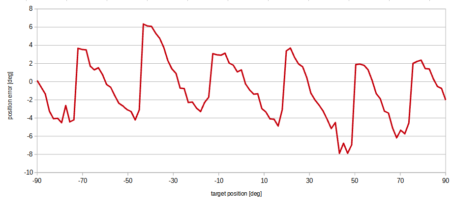
This is an inrunner in 12n4p configuration. This is why there are 6 torque ripple periods in the half of a mechanical rotation.
I am not interested in the absolute torque ripple values, but rather in position error values measured by using my normal position setting procedure. This way all required position corrections can be calculated for every motor target position.
1 Like
True, but a motor designed for too much torque can be more problematic than a smaller one, for example for the cogging. And, especially for the pitch axis, a smaller motor on the roll axis will create less inertia.
@MikeSierra2030 just a curiosity, are you using an absolute encoder?
Yes, a magnetic absolute encoder (AS5600) with analog output (which I’m sampling with ADC). I want to replace it with a better one, AS5048, with a digital SPI output.
The test of anti-cogging calibration of the motor 57BLY12530:

The feed-forward torque is normalized, i.e. referenced to the torque range <-1,1>. This is the torque compensation value that should assure reaching the motor target position and hopefully smooth operation of the actuator.
See how the wave reflects the position error chart a few posts above.
1 Like
That’s fantastic.
Thanks for the information about the encoder. I thought you were using an absolute encoder, otherwise mapping the torque as you are doing would require some fixed reference anyway.
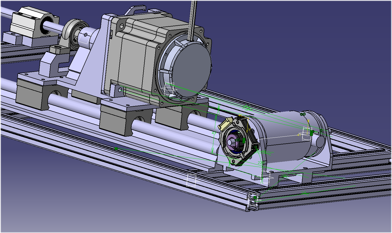
I have received a few bits and pieces, and put back my 3D printer at work, and I have assembled my idea for the roll axis. I’m still waiting for the delivery of the rexroth bars for the structure, but this is what it looks like:
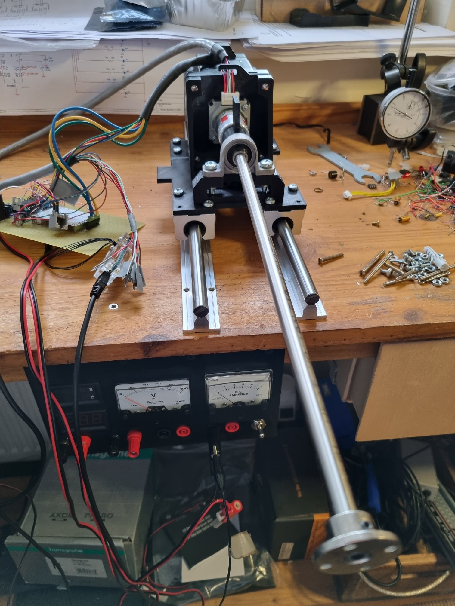
[the steel rod looks like it’s meters long due to the perspective, it’s actually just a bit more than 30cm  ]
]
Those rails are really smooth, but quite noisy. Once they are mounted on the structure I’ll see if some lubricant will improve that.
I’m thinking to try to get a normal brushed motor for the pitch axis, just to see the difference.
I need to mount the end switches and then I’ll try my own version of cogging mapping. Since I can’t install an absolute encoder on this motor, I’ll try a calibration using the end switch as a reference.
1 Like
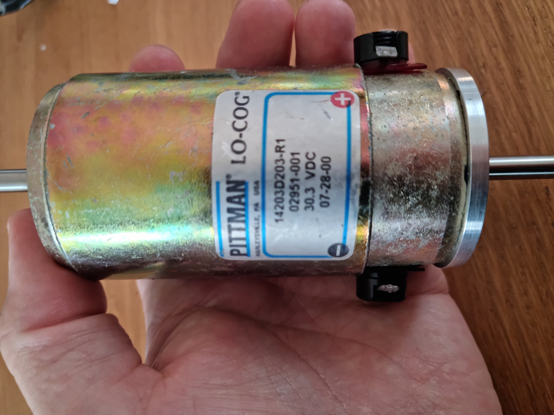
Oh, I have just found a DC (brushed) motor claimed to be low-cogging. I have ordered the 14203 model of this motor:
It’s 1Nm max, I’ll give it a try. It’s not really in line with my idea to build this thing using components that I can find “easily”, as this motor seems to be something that I can find only used somewhere… but… I’m curious to see how these low cogging these low-cogging motors are. Low cogging brushless are out there but I couldn’t find one single website to buy them, all manufacturers require to send inquiry for the quotation, which means that they are bloody expensive…
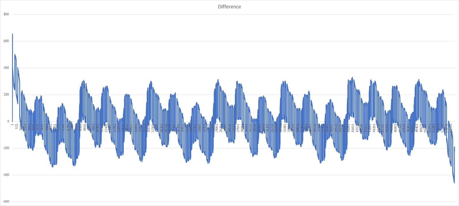
I have managed to plot the difference between the selected position and the position read by the encoder. When the controller is powered on, it searched for the two limit switches and then moves to the central position. I’m uploading the video of that sequence.
Then I have made a movement (which becomes very slow to send the data through the serial port, so it’s not in the video) going one point after the other from full left to full right, for a total of 270 degrees.
This is the plot of the difference between the commanded position and the position read:
Now… how to use that information, I still have to figure it out 
I’m using a small micro for these tests (I expected just to command the torque, nothing fancy…) so I can’t fit a 54000 values table for the cogging compensation. I need to reduce it in some way.
There, this should work:

1 Like
wow, I have just received this motor, it spins as smooth as silk. No sign of cogging at all.
It’s a plain brushed motor, I’ll try to use it for the pitch. I have found a similar one, depending on how it goes, I might drop the brushless. I haven’t see benefits compared to brushed for this application at the moment…
1 Like
After low pass filtering, there will be a wave with about 20 peaks and dips. Something like 200 samples should be enough. The values between samples can be interpolated.
I did it myself and getting a proper anti-cogging value at a particular motor position worked very well. However, there was a problem with the application of this torque compensation. My wave has got very steep slopes at some points and the motor accelerates like crazy at these points. Unfortunately, most of the time this torque compensation is higher than the torque calculated from the yoke deflection. The effect was worse than with no compensation at all. I’m dropping this idea at the moment at least.
This looks really good! I would be glad with such an effect. I have to experiment a bit more though.
I’m sorry to hear that, it seemed a good idea.
But indeed, implementation did not seem trivial at all. Any misalignment would lead the motor to start spinning, or any imperfection in the curve.
I haven’t tried yet, but as I said, I could not figure out how to make it work…
These and other considerations are what are making me thing to drop the brushless. Considering that we don’t have a specific torque to reach (so the precision given by the FOC doesn’t seems to be necessary), the only benefit of a brushless that I can see at the moment is the lack of wearing of the brushes. But the complexity of the control and the problem with the cogging are really significant.
Not that this motor is cheap, I paid it 40£ on ebay, but the actual model in production new is really expensive too… On the other hand, I couldn’t find one single place where they were selling no-cogging brushless, it seems to be all stuff for space or military.
Thanks  I can’t really take much credit to be fair, that is all done by the driver when it’s set in position mode. You need to set the PI parameters, but the compensation when it deviates from the position requested is calculated internally.
Unfortunately you can’t mix position and torque mode, so when it comes to implement the effects, I would need to use torque mode only and manually create the spring effect.
I have implemented a special version of a PID controller in software. I’m going to use the integral part in autopilot mode only.
Here’s the test of slowly changing sinusoidal reference input. The motor is following the requested position quite nicely except in the cogging points. I hope it won’t be a problem in the case of the motors I’m going to use in the final device.

Well, in your first plot you had up to 6 degrees of deviation, it seems a huge improvement to me!
I guess the ripple is still something like 6 degrees. Here the vertical scale is the normalized motor position in the range <0…1>, so this <-0.25 … 0.25> range in the graph reflects <-90 … 90> degrees of motor shaft rotation.
Next I’m going to test one of my gimbal motors. I want to use some gimbal motors for throttle and flaps levers (with haptic interactions of course).