I guess you want to make the pitch action on these rails by moving the roll motor with the yoke forth and back. How do you want to make the motorized linear movement, by the same time being able to move the whole thing also by hand?
My idea is to install the roll motor on a platform moving on these rails, and link it with a timing chain to the pitch motor. It seems to be the normal way to do it, see for example this project
I have been thinking in the past other approaches, mainly two pipes moving one inside the other, linked for radial movement but free to slide one inside the other, but with no mechanical tool available it would not have been possible for me to manufacture.
Today I was reading a bit about motors, I’m still trying to find what would be the correct motor to be used stalled. There is almost nothing online, or at least I have not been able to find much, but I found a useful information.
It looks like the stall torque is not the value that we need to look to see how much torque the motor can provide in our use case, but the start torque. In a few words, the stall torque is given at a specific speed, while the start torque is the torque that the motor can apply when is not rotating and depends on the coil ohmic resistance, since the motor is not moving and there is no back EMF involved.
Searching on what would be the best motor to work in these conditions, I can’t find any explicit information. The only clear advantage of BLDC over BDC seems to be the heat dissipation and the lack of wearing of brushes, and apparently there are motors designed to handle high start torque without overheating the parts involved in the commutation of the polarity.
Apart from that, I couldn’t find anything really useful, also because these data are very rare to find on the motor descriptions.
One consideration, though.
For a plain DC motor, torque is controlled by controlling the current.
A simple PWM driver controls the voltage, therefore the speed.
BUT when the motor is not spinning, setting the voltage corresponds to imposing a specific current based on the coil characteristics, since -as I mentioned before- there is no back EMF active.
So, for the conditions of a yoke, operating between stall conditions and a very limited movement, a torque control based on a simple PWM driver and current feedback should be sufficient.
What do you think?
I think that controlling the motor position and mapping the needed torque, to then use it to scale the control can be done. It is similar to the PEC on telescope mounts, used to correct the mechanical periodical error of the gears.
But it still would not be able to remove the cogging effect when you are moving manully the motor, I’m not sure how you would do that.
Indeed, while testing the TMC driver I found that the “I” component can be useful in some situation but it can make the system unstable very quickly. It is good when you have slow reactions, either because you are working at very low torques or because the load on the motor is high, but otherwise any substantial integral part will make the motor under-over shoot.
In the case of BLDC, 3 proper PWM waves, driving 3 coils, set the requested magnetic field vector of a particular angle and magnitude, therefore controlling the torque. Back EMF in not used here, because in the case of FOC all 3 windings are always driven. This is a real advantage of BLDC motors - in any situation you can generate the required torque. I don’t even use current sensing, yet it still works fine.
Anti-cogging torque map should assure a smooth moving to any position, regardless of the movement cause, that is if the motor is moved by changing its zero torque reference position, or by hand. Of course, in the latter case, there is extra torque generated (spring effect).
The spring effect is already working quite nicely.
In a way, this proves what I was trying to say. When you have no rotation, setting the PWM automatically sets the current (i.e. the torque) as in a simple passive circuit.
The driver I use requires current sensing because, when the motor is spinning, you need to read the current to know when to stop the PWM. When you implement it manually of course you can skip it -I didn’t have it either when I was trying the driver I made.
Hmm I’m not sure then I understand how you are thinking to implement it.
Are you suggesting to apply an offset torque based on the position?
Yes, for any calibrated position, a proper offset torque should be applied to counteract the cogging torque. The “user torque” should be added to that offset.
I see. But how do you know the direction of the torque that you have to apply?
The cogging is just a resistance to the movement, not something that pushes in a specific direction. So, when you are moving manually the motor, you need to read the direction of the movement to know the “polarity” of the offset, otherwise you might end up doubling the cogging torque instead of canceling it.
In theory, to know the direction, you need to use the encoder, but either you make a very fast and sensitive reading and become subject to the noise or you filter enough to make sure in which direction you are moving and at the beginning you will be feeling the jumps anyway.
But it might work, I guess it’s matter of trying it.
By calibration procedure and creation of anti-cogging torque map.
Cogging does locally push in a specific direction. Let’s assume the motor is settled in one of cogging “detent” positions. It is stable there. When moved a little to the right, some torque to the left is appearing. The controller must apply the same amount of the torque to the right to counteract the cogging torque and assure a smooth movement. This anti-cogging torque will have various directions and magnitude in each sampled position. Therefore the anti-cogging torque map should get sufficient number of points. Possibly a kind of interpolation should be applied between the calibrated positions.
So, I have been searching for mechanical components, this is the idea for the roll axis assembly.

I have included a mechanical stop for a total 300 degrees movement, with limit switches for the calibration:
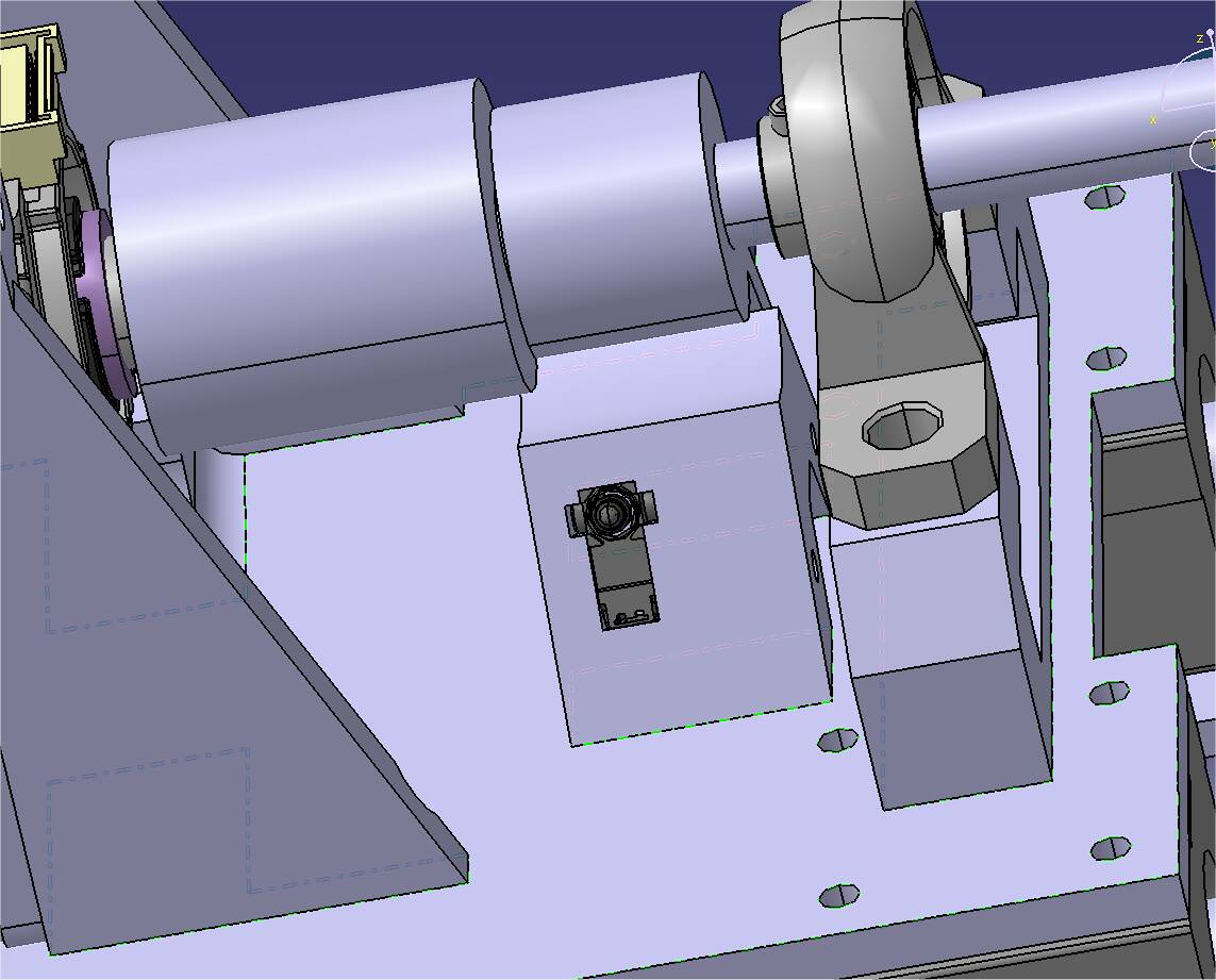
The other motor would go on the side, with the belt attached to the platform.
It should all 3D-printable… at least for the prototype.
1 Like
@MikeSierra2030 , do you already have an idea of which motor you are going to use? I’m having a lot of problems in finding mechanical parts for the 1/2" shaft of the 86BLS71 motors I have, everything is in mm (unsurprisingly…) and I might get two new motors. I was wondering if you know what to search for a low cogging motor, it’s not exactly something that you find in the description…
I have only found the information, that for high torque and low cogging, the best motors are outrunners with relatively high numbers of slots and poles. I’m interested in outrunners 8308 90KV and 8318 100KV, both in 36N42P configuration.
Can’t find anything of that kind ![]() are you planning to buy them from China?
are you planning to buy them from China?
I found this while searching for the motor, it might interest you:
I wonder if something like this would be of any good, I can’t find any datasheet…
https://www.ebay.co.uk/itm/373543019028?epid=20038978874&hash=item56f8e62214:g:hHkAAOSwLSxe2npQ
Possibly. Something like this one: 61.0US $ |Eaglepower 8308 Brushless Motor Kv90 130kv Kv160 180 205kv High Power Loading Motor For Large Agricultural Drone Hly W9225 - Parts & Accs - AliExpress
This one is 36N40P, which should be even better for low cogging.
I already know this document. My solution, I want to test, is a little different, but should lead to the same results: motor position-dependent anti-cogging torque correction.
Possibly yes, but it would be an overkill for my needs. I think I don’t need so much power (torque).
The motors I mentioned above are Chinese copies of 9225-90KV and 9235-100KV.
Nice motors – just watch that their high torque does not break you hand !!!
2.3 KW Motors !!!
This is why the name of my project is “Wristbreaker” ![]()
“The Little Force Feedback Yoke that could” ??
When I look at the relatively small, low torque motors on my Sidewinder II, which could be considered to be “adequate”, one wonder how much one would be Fighting with some of these more powerful servo motors !!
It’s true, it has been one of my biggest doubts since the beginning.
Yesterday I was looking at the motor used on the Simucube, since they have a direct drive steering wheel and they said that it has no cogging. Well, it turns out there is even a wiki page:
https://granitedevices.com/wiki/List_of_motors_for_SimuCUBE
and those motors deliver 20-30Nm. And they cost a fortune.
But… what you say it’s correct: a sidewinder has a plain, simple, small brushed DC motor (with no detectable cogging on the joystick) and the torque is what you can deliver on something that is not fixed on a table. But I have seen videos of force feedback steering wheels that bend the tables where they are fixed, and that seems quite eccessive.
Add this to the fact that the simulator is only giving a 0-max indication of the torque, so no real value that you need to generate. Therefore, unless you do the work that @tsaG13374551 did some time ago of getting a real plane and measure the force generated on the stick applying weight on the control surfaces, or we are all just guessing.
This is one of the reasons why I would like to build the mechanics of the yoke once I can restart working on this project. I will be able to try different motors and see what makes sense to use.
Probably even for the roll axis in direct drive what I have is too much: I’m using it at 30V 2A max and it is difficult to hold it.
Thank you @MikeSierra2030 for the indication of the motor!