Exactly. If the rise of the torque at a certain position is too abrupt, the shaft will bounce or even kick violently. A very nasty feeling and nothing like a mechanical stop.
I can see 2 solutions: either make a mechanical stop or gradually apply so much torque that further movement seems very difficult (yet still possible).
I’m not sure if the second solution would work, if you need to apply that much torque to make it difficult to move and do it gradually, you would either start to “feel” the stop too early or allow too much movement.
Maybe the simple mechanical stop is the best solution.
But… I’ll make a try.
Done. Far from pretending that there are no better ways, but applying a proportional torque to pull the motor back if it passes over a certain position (sort of) works if then you are holding it steady.
The problem is that once you have even a small lever due to the yoke (at the moment I have a bar 20cm long, so smaller than a yoke), the torque of the motor is not sufficient to stop you from further rotation.
If you keep holding the motor and move it back, it’s ok. But as I suspected, if for any reason the motor is released while applying a high torque, it bounces back reaching the other limit and starts oscillating back and forth. To damp the oscillation, either you have to set a very low torque (which makes it useless) or a very slow PI (which will make useless the effects).
So my conclusion is… I have complicated my life enough on this, it will be a mechanical stop ![]()
1 Like
Good news! My bldc motor works fine with FOC algorithm and a “spring” model. The applied torque is proportional to the “position error” relative to the reference “zero torque position”. Maybe a kind of PD (proportional+derivative) filter should be applied to damp these small oscillations. Anyway, these are very promising results.
1 Like
Yes, that looks great!
If you want to dampen the oscillation you should make the system slower working on the PI, maybe even on the D if you implement it.
The TMC can do the same selecting the position mode instead of torque mode, but then it would not be compatible with the other effects.
Be careful with that piece of aluminium mounted on the motor, I had my hand slapped a couple of times by my piece of plastic and it has not been pleasant.
Have you been able to find a solution for the cogging?
Although this motor has got quite perceptible cogging effect, the lever plus FOC algorithm make the effect almost disappeared when driven. Eventually I want to use much more cogging-friendly motor (92 mm outer rotor with 36 slots and 40 poles).
This is a simulation of force feedback. The zero torque position is dynamically changed with the potentiometer. When holding “the yoke”, I can clearly feel the forces.
1 Like
yes, that is what I also have noticed. I was more referring to the situation where you have no or very little torque applied.
As you say, probably there is the need of a motor designed for this use.
Here are the next tests and a few conclusions:
- Torque is proportional to gain * „position error”.
When the gain is too small, there is too little torque close to the middle position, and there is too much yoke play in the middle position.
When the gain is too big, yoke oscillations occur, up to a point when system becomes unstable.
The stability depends on the yoke inertia.
Some solutions help:
2. The derivative component is added to the proportional one. Oscillations have been suppressed, but the yoke becomes a bit restless. The position encoder readouts get noise, which is amplified in the derivative component. The derivative component can be filtered, but some small vibrations are always there.
3. The torque gain is not linear. It is higher close to the middle position, and lower when the yoke is heavily deflected. This solution solves the effect of having a too small or too big gain.
4 Solutions 2 and 3 can be applied together, but they must be tuned in the final hardware setup.
5 The yoke should be balanced on its own. Otherwise, the motor must apply some non-zero torque to hold it steady. This non-zero torque may cause some unwanted vibrations (permanent attempts to hold the target position).
6 Despite my motor under test is not very big, the forces can easily move my entire testbench. The final device needs to be solid and well clamped.
1 Like
Interesting results. I had to put everything on hold because I’m leaving tomorrow.
What kind of motor are you using? It looks rather small compared to the one I have.
All the observations you are doing are correct, I have seen the same effects/problems. On the other hand, I think there is a danger to try to deal with situations that won’t be present with a flight simulator.
I mean, when I did the test of the FFB part, receving the actual control from the simulator, I have seen basically three effects: sine (for the vibration), contant force and spring effect. What you are trying here is basically the spring on the central position, but in any case all effects were rather… smooth. No sudden bumps to one position, no sudden high forces in one direction -at the end, there is the mass of the plane to filter the disturbances. I have never seen the input reaching the maximum scale.
One issue that I agree is there is the central position. Since the input of the system is the force, and not the position, when you get close to the central position and the force is proportional to the distance from it, you will reach a point where your yoke won’t move and you will remain with an offset.
You can make the mechanics as smooth as you want, but there will still be the cogging of the motor.
If you remember, a few posts ago I was mentioning that the spring effect is automatic with the controller in position mode, and that will take care also of the low torque in the central position because the “I” part of the controller will end up giving enough torque to reach it. But all other effects are torque-based and not position-based, if you understand what I mean.
So I was thinking, if the controller transforms the torque input from the simulator into a position input for the controller, you could be solving both stability and central position problems.
For example, your position is X. The P control gives you 1Nm each 100 steps away from the desired position. So if you want to apply a constant force of 0.1Nm, you set the central position to X+10 and update it while X is moving.
Or, if the controller activates the sine effect, the position will the X + amplitude * (sine(requested_frequency)).
Something like that.
Of course this could work on the TMC that has a position mode, I’m not sure if it would be a good approach with your controller.
By the way, I have also noticed the noise on the encoder, which I found rather surprising. I suspect that the noise could be of one position when you are on the threshold, but what actually you are (and I am) reading is an actual movement of the motor, too small to be seen, but sufficient to trigger a 2048 or 4096 position enconder.
I have not decided yet if using the encoder as reading for the yoke or adding a traditional potentiometer. This issue with the reading noise is making me think to keep a potentiometer. What do you plan to do?
I think my system is going to be a bit different (if I ever build it).
There is the central position. The motor is reaching it during the startup procedure. I can then deflect the lever, let say ± 90 degrees from this position (it can be more if there is no mechanical break).
There is also something like “zero torque” position. It can be dynamically set anywhere in the operating range. The motor, when not externally forced, will settle at this position. Manual deflection from this position needs application of external force.
The “zero torque” position is going to be constantly moved by the simulator based on the value of many simulator variables. Therefore the pilot will feel on the yoke factors like trimming, air forces, gear and motor vibrations etc. It is my duty to translate some simulation variables into my yoke position.
Currently the yoke operation is quite smooth up to the limits, so motor cogging is no more an issue.
Yes, this is how it works for me. I call it “zero torque” position though. The central position is just the center point of the operating range.
I’m using a 12-bit magnetic encoder. It gives 0.043 degree output noise. I’ll be using a slightly better 14-bit encoder soon.
Using a potentiometer won’t solve the noise issue. You have to make A/D conversion, which is also affected by noise.
I see.
But how that would work when you start receiving the inputs from the simulator with the torque to be applied? In general, the return of the yoke is controlled by the simulator, depending on the plane and flying conditions.
But yes, this is similar to the idea I had in mind.
I had three potentiometers in my other test setup and with some basic filtering and some decent routing I had a very stable reading on 12-bits, which is more than what normally joysticks use, with no significant loss of dynamics.
In a real plane, when a pilot takes his hand off the yoke, the yoke will settle at a certain position (plus rapid turbulence and various vibrations). This is what I want to achieve by calculating this position from various simulator variables. This position is generally not a center position. To make a straight and level flight a pilot must move his yoke by applying a certain force (unless the plane is trimmed). The amount of perceptible force is not a big deal. It just should be quite real. But the current position of yoke is the factor that counts.
Yes, I agree. But since you don’t have the input from the simulator to tell your controller what is the central position, how are you going to determine what is the “rest” position? You just keep the central one (I mean, the central position on the two axis)?
But I do have it. I can read the current position of a control surface (e.g. elevator) from the simulator. Since the pilot’s yoke is wire-connected with this surface, I have to set according position on my yoke. The rule is simple: the movement of a surface is translated to “zero” position of the yoke. The movement of the yoke (by applying a force) is translated to the movement of the surface (as it is done in all non-force feedback joysticks). Easier said than done, but this is what a piece of software can do.
Ah in that case you are ok. But I would have no idea how to interface anything to the simulator… I know that there are programs out there to do it, but I never had the chance to learn them.
Maybe, in the future…
But for now my only interface with the PC and with the simulator is the standard USB HID protocol and whatever the simulator gives me (trough XPForce in this case).
One little thing I can fix very quickly is my shaft position encoder response. Currently, I’m using 12-bit AS5600 encoder, which gives me a kind of popcorn noise (random peaks). This translates to a kind of restless yoke behavior. A simple median filter (size of 3 is enough) eliminates this noise:
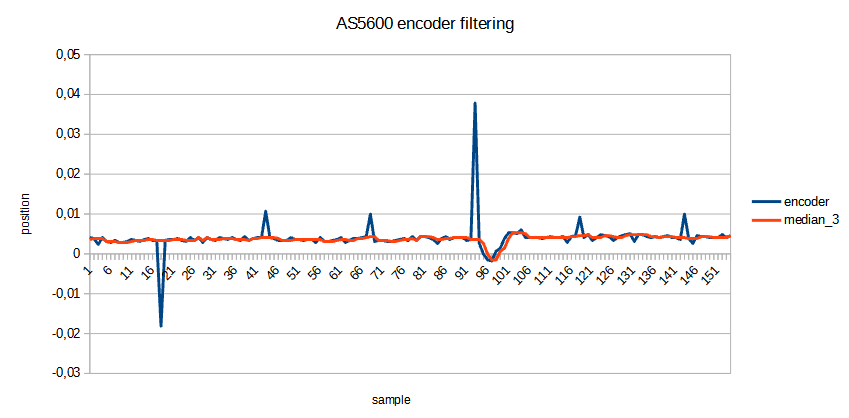
Position means yoke roll position read from the encoder in the nominal range <-0.25, 0.25>, which reflects <-90, 90> degrees of yoke deflection. Peaks seem to repeat in constant intervals, but it is not a rule and they are of random time and value. I’m going to upgrade to a better encoder (AS5048) soon.
1 Like
The spring action is nice and smooth. Two tricks described above helped a lot (torque calculated from error by using PD controller and non-linear torque shaping). More testing is needed though.
However, the motor action is much worse when its zero torque reference position is slowly changing. In such a situation motor is working with relatively little torque, and the torque cogging effect is apparent. In this test the reference position is slowly changed by sinusoidal function:
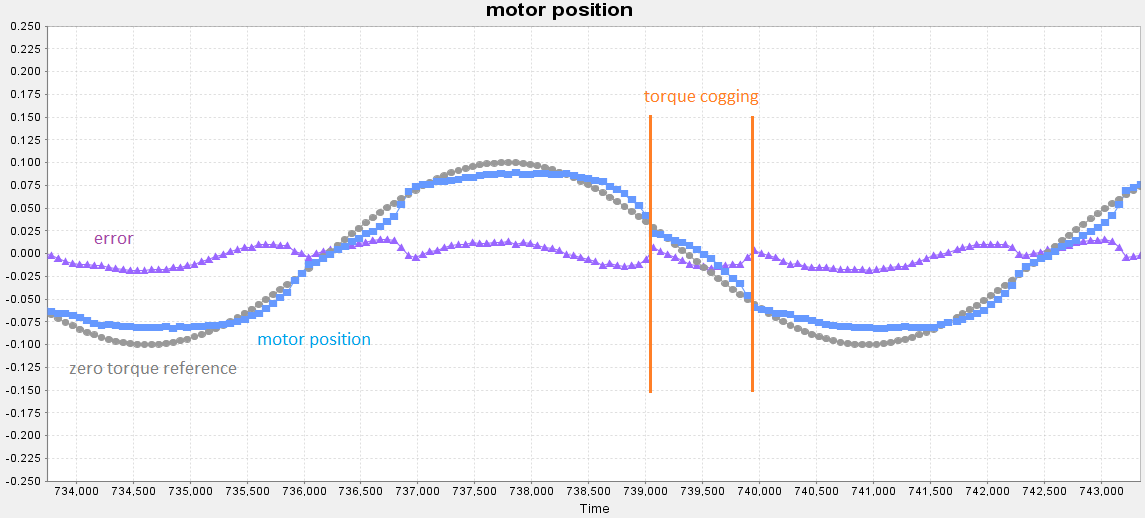
The motor shaft position is following the sinusoidal curve quite nicely, but 4 torque cogging points in every period are apparent. The effect can be noticed in this video:
A better motor may make a huge difference here.
1 Like
I wonder what would be the result of the same test with a brushed DC motor…
I’m looking while I’m away for the mechanical structure. I found two linear rails on ebay at a decent price, I might do the roll axis direct on the motor.
I will investigate using cogging torque ripple compensation software techniques. They may solve this problem even in the case of rather poor motors.
BTW I have also checked the application of a full PID controller. The integral component assured catching the required motor position, but of course, also spoiled the spring action of the yoke. It was a funny feeling when the motor was trying harder and harder to come back to the reference position.