I’m not sure my solution can be anyhow applied in your case since you’re gonna use different software to communicate with the simulator. Anyway, here are some rules I have to follow to reach the goal in this particular case:
I’m using the SimConnect variable “GENERAL ENG THROTTLE LEVER POSITION:N” (where N is engine index 1…4) to read and write the lever position in the simulator.
This variable value read from the simulator is used as the current reference position for my “throttle” motor. This value is read in every simulator frame, which is usually with 30-60 Hz frequency. This is the feature of SimConnect and the simulator - variables cannot be set and read more frequently than the main simulator loop. But it’s sufficient.
Although the mentioned variable (and many others) can be set in every frame, it is not a good idea, because this way the variable change initiated in the simulator (with keyboard and mouse input included) is blocked (permanently overwritten by input from the yoke). This is why the variable should be set only on its value change initiated by the yoke end. To achieve this, the next 2 features have been applied:
For changing the lever position and sending a new value to the simulator, a certain amount of force must be applied. If the force is not sufficient, a new value is not sent to the simulator and the lever position is not changed. It also assures the lever is not floppy. I feel I have to move quite a piece of hardware.
If the throttle lever position change is initiated by the simulator, the new position values are not sent back to the simulator until the new position is settled (i.e. the simulator completes changing the position).
Thank you for the detailed description!
Indeed, my situation will be different. As I’m going through the standard FFB USB interface, I won’t get any setting from the PC, except the effects. The point where I will need to have two systems following each other is when I plug two yokes together to fly as pilot and co-pilot. Here, they will have to follow the same position as if they were linked together.
My idea is to use a fairly strong spring effect between them to force them in the same position. If one of the two is free to move, it will follow and cause no interference. If one is being held in a different position, they will both feel the force to move until they reach the same position.
Only one will still be controlled by the PC and will pass the effects also to the other, so they will be experiencing the same feedback.
The only limitation is that only one, the master, will send positions to the PC. But I don’t know any way around that.
Yesterday I have sent the USB board PCB to print, I should have it in a couple of weeks. In the meanwhile, I’ll work on the main plate for the mechanics -I’m still not satisfied- and on some other details. Once I get the last board… the fun will start
Slightly off topic, but microchip microcontrollers seems to be out of stock everywhere, with lead team of one year for the next shipment. Luckily I had a few in my drawers, although I had to go for a smaller model. It’s quite impressive, I have never seen a shortage of components on this scale.
I’m wondering what the source of FF information is in the case of FFB USB. As I know MSFS does not support any FF data. I guess Bruner FF yokes just read some flight parameters and calculate desired FF data in their interfacing software.
What’s worse for me, some flight variables are not updated at all in some modes. Possibly you have noticed, that the yoke in the sim is not moving at all even during stormy weather. So are not the yoke position X and Y variables. In a real plane the yoke should move until a pilot holds it tightly.
When the autopilot is engaged, the yoke is moving in X axis, but not in Y axis. Only the trim wheel is moving (and only the trim variable is changing). Such issues are really not helpful in FF development.
A kind of inverted effect of Airbus sidesticks. There both sidesticks are not “linked” together, but the input is taken from both (so they are averaged in some way - if one is moved to the right, the other to the left, the plane can still be flying leveled, despite the conflict alarm generated).
But this is possibly all you can do. Both yokes shouldn’t be deflected by hand at the same time.
Currently, it is the problem not only for the consumer market but also for big professional electronic producers. It was just today that I was advised at work, that the new boards I’m developing software for, are delayed several weeks because of electronics supply shortage.
True. I use XPForce that interfaces with the simulator and passes the effects on the standard USB protocol.
It could be, I don’t know that system. But if they are recognised as USB FFB devices, they either have their own driver, or they are constrained by the standard HID interface, which includes only effects towards the device and axis readings and buttons toward the PC.
Oh really? I didn’t notice that. But I just tried a short flight and there was clearly some significant wind, as the airplane was going on the side, but the yoke was not showing any effect. So I guess it’s indeed difficult if you are just trying to replicate the controls movements to create the FFB effects.
I have been talking with a friend who was working on commercial flight simulator about this. She was saying that it depends on the aircraft, but -I don’t remember if it was on Boeing or on Airbus- when there are conflicting inputs the on board computer detects it and raises an alarm, and what is transmitted depends on the situation. But of course, if we are talking about fly-by-wire there are a number of options, here the controls should be mechanically linked together, so my idea is to make sure that they behave as much as possible in that way.
Yes, I’m not surprised, it’s everywhere. Working on space project I’m used to 30-50 weeks of lead time, but on commercial electronics… nope. What is happening with cars is just unbelievable. My car model, used, is being sold now at a higher price than when I bought it already 2nd hand three years ago. If I sell it, I could make money out of it. Never seen anything like this, they said that new cars are now on six months lead time due to shortage of electronics.
@MikeSierra2030 I don’t know if you are following the thread on FFB support in the wishlist section, but this post is interesting and on the same topic we were talking about today:
As a proof of concept, I want to test a DC motor for yoke pitch action. I don’t believe in big success, but we’ll see.
I’m testing a small 6V DC motor with a gearbox. If tests are OK, I will want to use a little bigger motor with a worm gearbox. A linear motor can be also possible, but linear motors are usually too slow (not exceeding 160 mm/s, but according to my calculations I would need something like 500 mm/s).
Anyway, a motor with a worm gearbox cannot be rotated by an external force, so a kind of user input sensor is needed. I’m going to use a load cell for measuring the forces from a pilot’s hand. According to my previous tests with load cells, I can expect some troubles here.
So far I’m spinning my motor in an open loop, and the first issue had to be solved here. DC motors need a certain amount of voltage to start spinning. This value depends on a motor and its load. But it can be easily corrected at least.
Closed-loop tests are coming soon.
I’m not sure I would recommend a gearbox. I have got from ebay a dunkermotoren with a reductor and, apart from making it a bit hard to move it manually, the reduction adds a lot of inertia when you make it spin manually. It’s a rather big and heavy motor though, so you might not notice this effect on a small one.
If you can find on ebay some second hand no-cogging motor, give it a try. With some luck, they are reasonably cheap. I’m using a maxon 148866 on the roll axis with a 1:3 reduction made using a 20 teeth and 60 teeth pulleys and the torque is reasonable. On the pitch I’m using a lo-cog pittman motor and that is sufficient to pull the yoke off your hands.
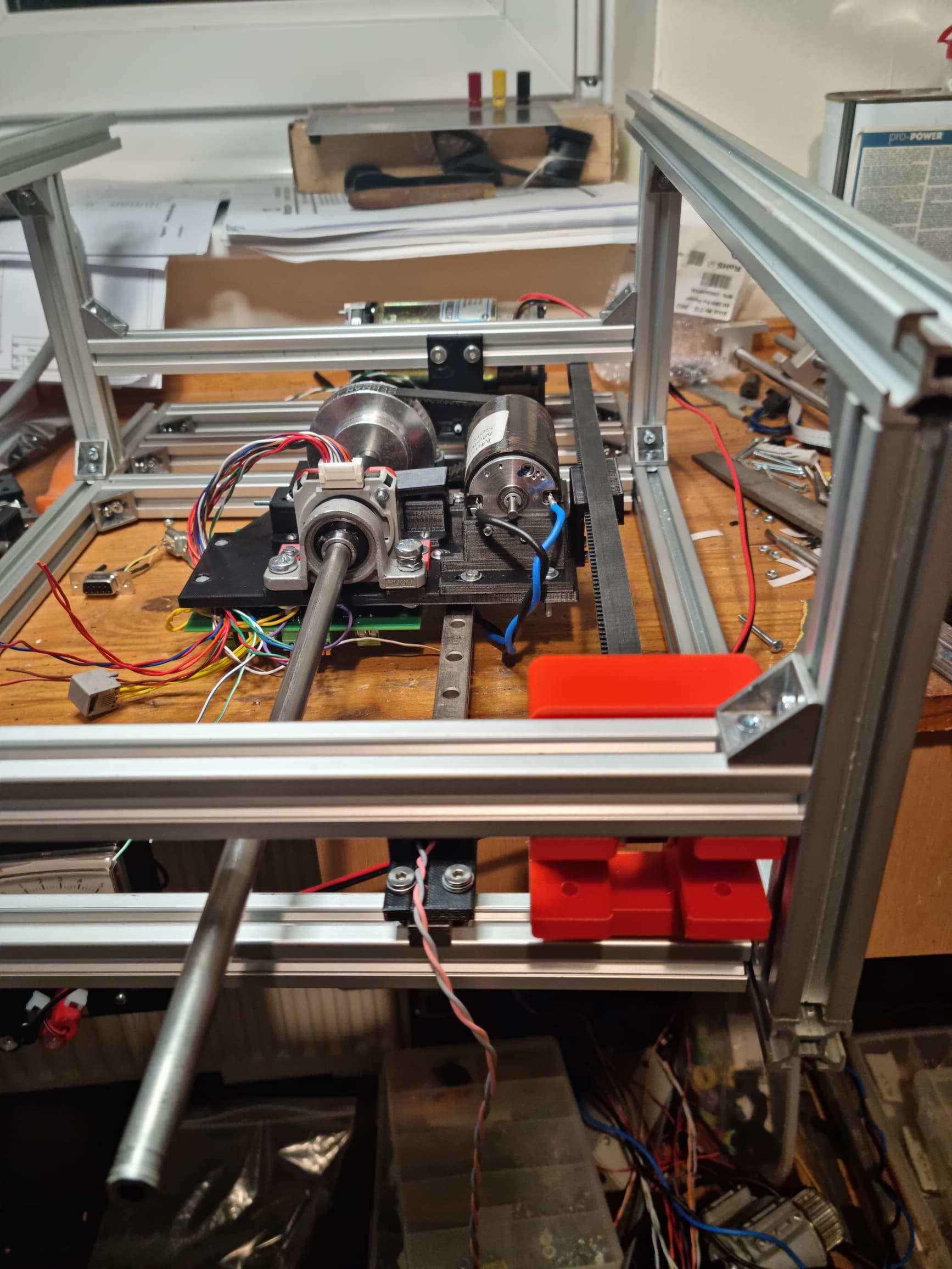
By the way, on the mechanical side, I’m re-designing the whole assembly to mount it on a single linear rail. I have got one of those for 3D printers and it is incredibly smooth, silent and rigid. In that way, the overall height of the assembly is reduce further to 70mm. It looks promising, and better than the round linear rails.
But I do not want it to be moved manually. In no situation. This is exactly what I want to test. A DC motor with rather a big reduction ratio gearbox. It should hold its position when not driven. Instead of the manual movement, the motor should be electrically moved to the position calculated from a force sensor.
I have already done such tests with RC servos before, but they were too weak.
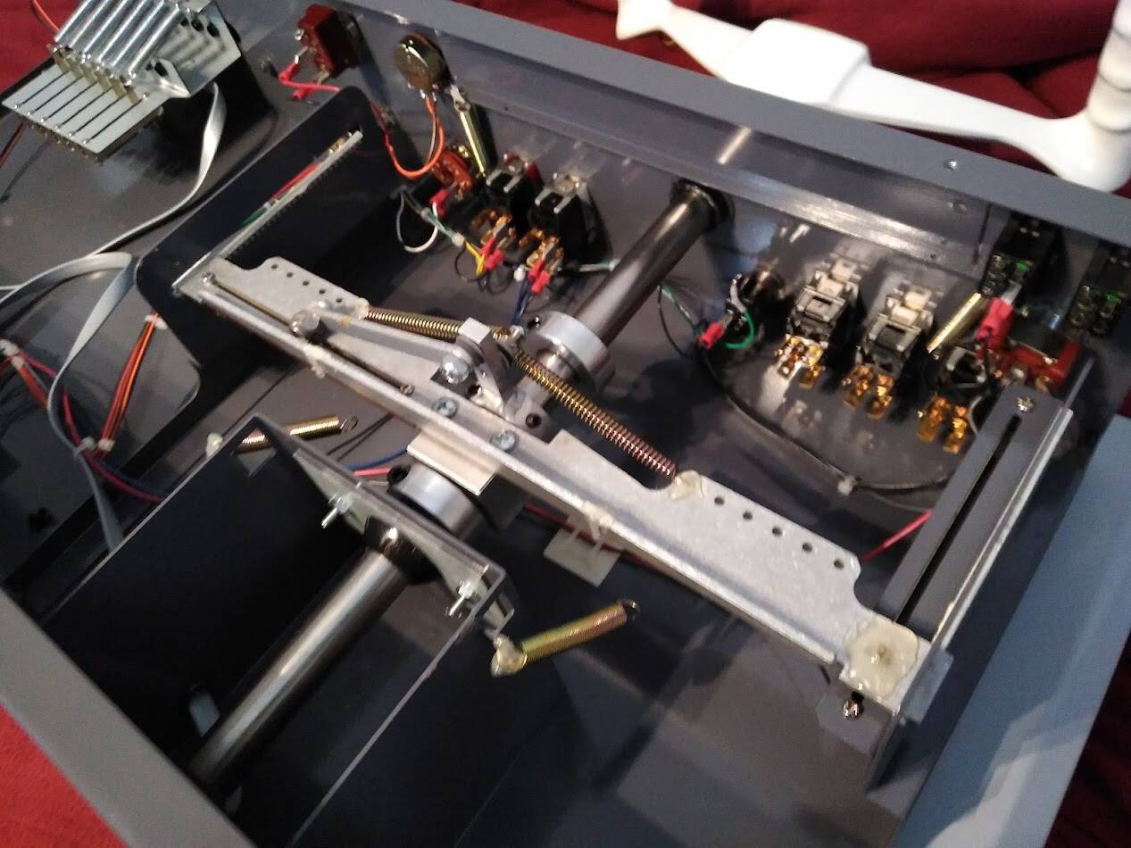
Here is my new mechanical setup. Consider that the height of the frame was the original height of the assembly with the brushless motor… quite a reduction!
It’s all very smooth, except for the bearing of the yoke axis. I think it’s a mix of cheap chinese bearing coupled to a cheap chinese steel rod, which is far from flat and regular. I’m trying to improve it a bit with some sanding but well, sanding steel is a rather boring job.
Without the front bearings, anyway, it’s really smooth. I need to make a support for the second driver board and I’m ready to test the two axes. Next week I should get the PCB for the USB board.
It works really well, it’s as smooth as if it were floating on air!
But I had a problem with the steel rod, the one where the yoke is fixed: the linear bearing was getting stuck in a few points. I thought it was the bearing, but it turned out that it was the rod that was far from regular —classic ebay junk. I spent some time adjusting it and now the bearing moves freely, but I might change at some point.
The thing is, with one linear rail at the bottom you avoid all problems of alignment between two rails and reduce the friction to the minimum, but it’s not stiff enough to run without a bearing on the yoke rod too. At least, using one of these small linear rails.
But since I want to be able to pass cables through the yoke rod, for buttons or whatever I might end up installing on the yoke, I can’t use one of those solid, precise steel rods that are sold for linear rails. And I can’t go for something too wide either, or I won’t find bearings and couplings for the pulley and encoder. So I’m a bit stuck with part quality, part availability… and cost, obviously.
Search for rotary linear bearings. I’m not at my computer or I would give you the link to the website. They have a very interesting bearing that you could mount to the frame and forgo the linear rotational bearing that is mounted to the sled. The quote that I received for a 1in bearing was $78
I see, at least on ebay they seem to be common in US, but nothing available on this side of the ocean. They are quite expensive too…
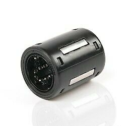
I’m giving a go to a SKF LBBR10, it’s one of these:
That looks like a linear bearing. It won’t allow for rotational movement. So I don’t know where you are going to use it.
I already had a Saitek yoke so I bought a MSFFB2 stick and am installing the guts of it into the existing Saitek yoke. I am using 2 self-centering thrust bearings Amazon.com?
a needle bearing Amazon.com?
and the linear slide.
I am hopeful that I will not have to use the rotary/linear bearing because, as you said, it is expensive ($78) https://www.e-lrb.com/
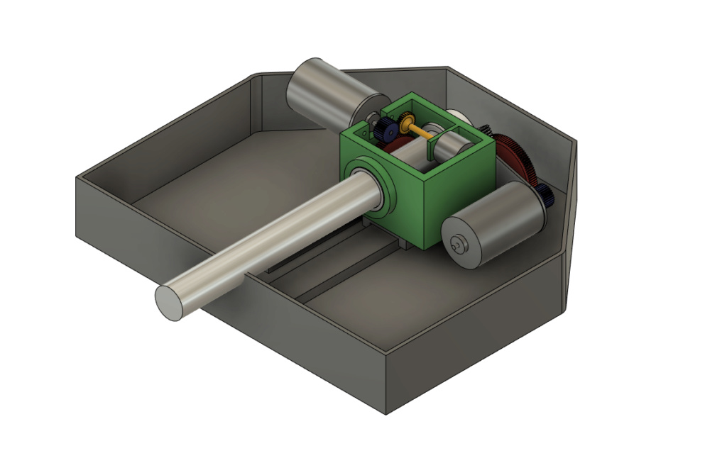
Here’s a pic of the design. The first piece is on the printer now. I’m making the gears out of nylon using a .1mm nozzle for strength and to be able to get the detail of the teeth; so it’s going to take a while.
Yes, they are linear bearing as you say, but they do allow rotation.
The needle bearing you mention, that doesn’t allow sliding, does it?
In your assembly, how does the pitch axis work? I understand that the motor is fixed on the green box, but how is it moving the axis back and forth?
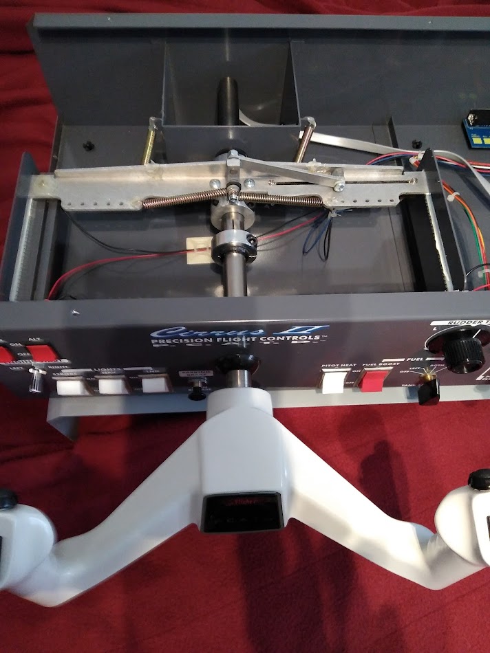
Working on a ffb yoke. My 4th one… All are based on the MS FFB2 boards. Repurposing these Precision Flight Controls flight school simulators. I am going to try a rack and pinion drive for the pitch and timing belt on the roll. I have been watching your thread…