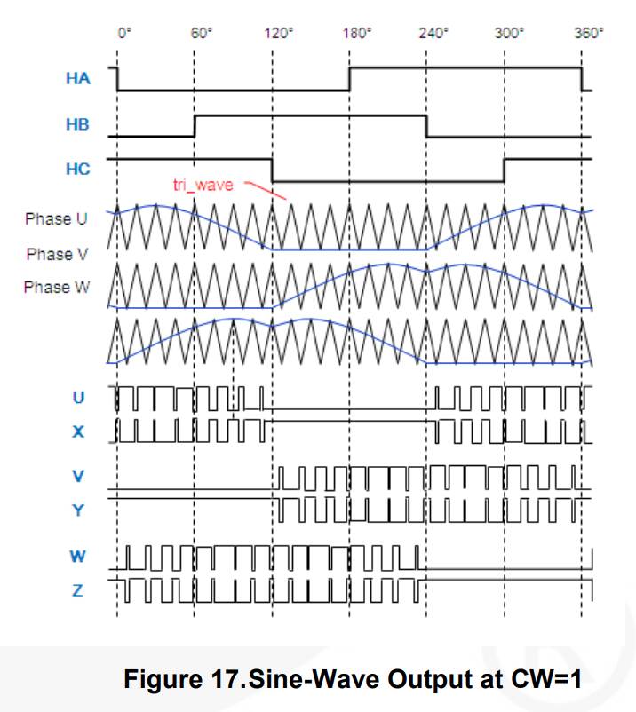
Yesterday I managed to find a datasheet with the hall sensor output and waveforms, so I could finally understand the right order.
Still, although they work now, I can’t get them sinchronized properly with the hall sensor. They keep jumping back and forth, and I don’t really understand where the error is. The motor moves of two “quadrants” (from 180º to 300º in the diagram, apparently) and jumps back, but in the code the sequence at each change of the hall sensor seems to be correct.
I need to work more on that.
Why do you want to use them? They are unneeded in this application. All you have to do is to read one row in the “sinus” table and drive 3 phases with the PWM values. If you want to rotate the motor by a certain electrical angle from that point, you take another proper values from the table. This way, every time by moving down in the table you rotate the motor in one direction, by moving up you rotate the motor in the other direction. If you skip n rows in the table, you rotate the motor faster. You shouldn’t however skip more than 90 degrees of electrical phase in one time.
If the motor is moved by an external force, let say between 10 and 50 electrical phase points, by using Hall sensers, you are not able to decode this movement. Yet still you have to set respective phases to the motor, plus some required phase change for generating the feeling of force. For this functionality, you have to use a good resolution encoder (at least 12-bit, instead of 3-bit Hall sensor).
Hall sensors (like in this diagram) are used for generating BLDC fast spin. In your application, you need relatively precise slow motion or holding the motor in a desired position.
I know, I know. I’m trying to go by steps until I get it working, and at the moment I still don’t have an encoder, I’m just trying to move the motor right now.
The transition on the hall sensor should still mark the different sections of the sine waveforms, so I was trying synchronize the two parts together.
Once I’ll get the new motor (a stepper, though… I just can’t find a BLDC with an encoder or an encoder that fit this motor that I have) with the encoder I’ll do as you say.
You can still get rid of the Hall sensors. Just generate your table for PhaseU (or PhaseW) between 0 and 120 degree. The values for other phases and sections are just a kind of mirrors and shifts.
Then create a variable “current phase” with values 0..360. According to its value, read the table and calculate the requested PWM values of 3 phases.
When you increase or decrease “current phase”, the motor will move. This is an entirely open-loop scenario. Just by adding an encoder later and calculating the desired new phase, you’ll change it into closed-loop.
These Sensors have a opening and can be used for shafts up to 14mm (which I have), of course there are also 8mm adapters. I am not sure yet if I will connect them to the front, or to the back of the motor. The motor does have a little bit of space in the backshell, my first idea was to replace this backshell with some kind of adapter… Lets see when the motor and sensor arrive here.
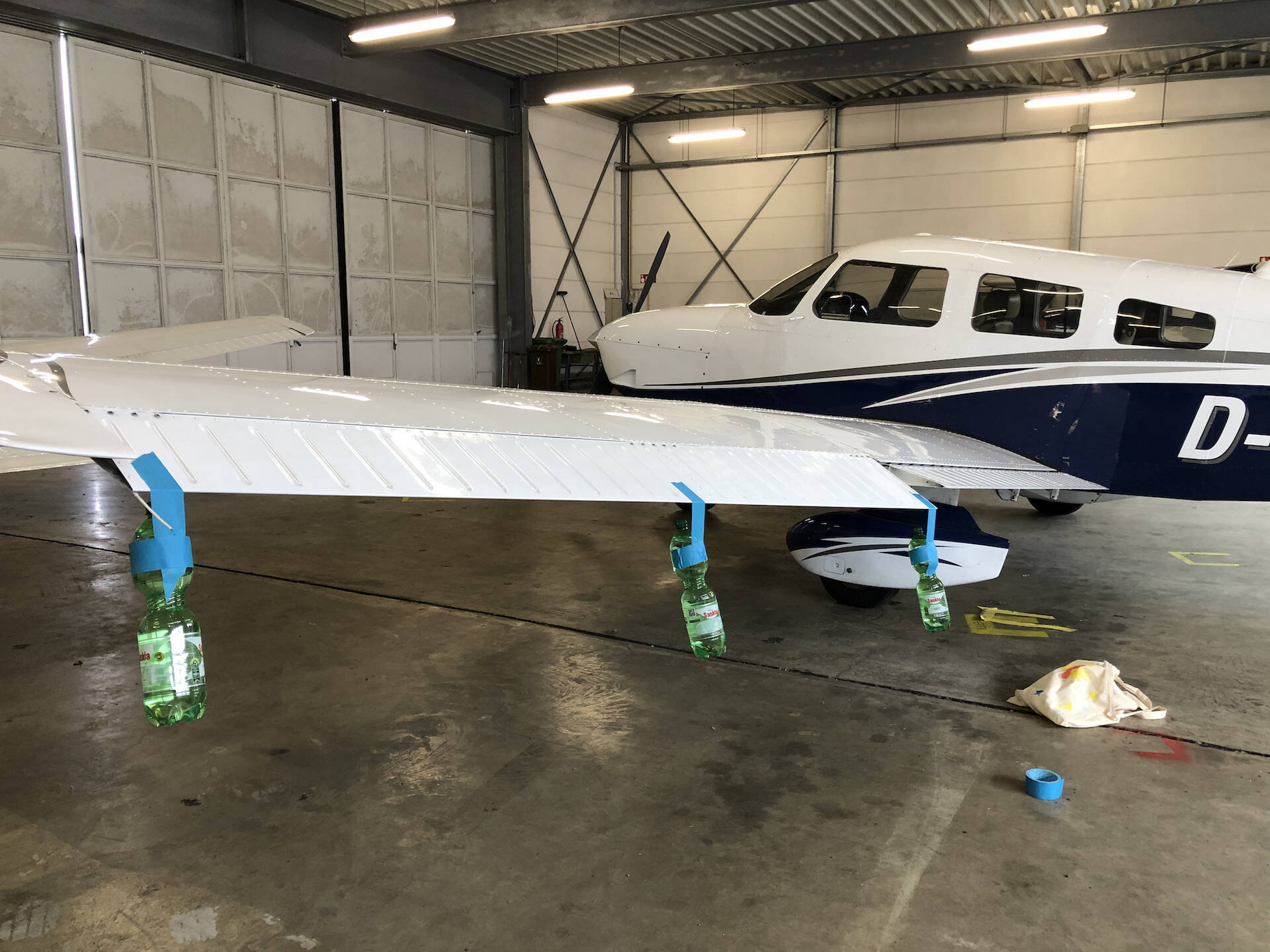
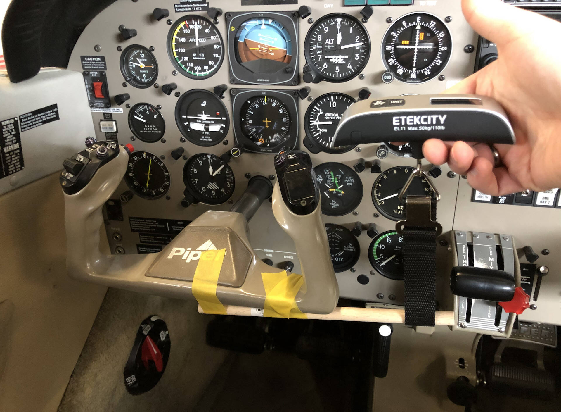
I have been at the airport today to do some testing as proposed. I attached 3 bottles á 1.52kg on on side of the Aileron. I should have done the calculations before because it looks like this was way to less . The frictional/damping loss on the yoke was so high that it barely moved as I attached the weight.
Nevertheless I created an excel sheet with some calculations.
For the next try I would do this test with two persons and scales. One in the cockpit and the other on the aileron. Pull x kg on the yoke and see what it does on the aileron.
I uploaded the excel file to wetransfer. Unique Download Link | WeTransfer
According to the current calculations, the maximum force required would be around 9,4Nm (Pa28 at 110knots with 30° Aileron deflection).
My motor is rated at 12.5ChinaNm so, Im also not sure about the direct drive implementation yet…
I think I will give it a try.
Sorry for the late reply, I have been a bit busy on other things…
Ok, if I haven’t go the datasheet wrong, the absolute encoders have a maximum hole of 8mm, while the incremental encoders have a hole of up to 14mm. I was considering the absolute encoders, that is why I was mentioning the 8mm shaft maximum.
When I opened my motor, there was some space at the back, but the shaft wasn’t coming out of any useful length.
I absolute love it
I have received the stepper motor with the encoder, but I still have to try it.
I kept checking what was going on with my brushless, because the movement wasn’t smooth at all even with the sinewaves. Apart from a dying mosfet, I found that the protoboard kills so much high frequencies that the 40kHz PWM was getting awfully distorted and the final waveforms were rubbish.
So I reduced a lot the frequency just to try and managed to get what looks like a clean sine between two phases, but I still get a jump periodically at polarity change. I suspect that low duty cycle PWM is still eated out from cables and parasitics, so I’m going to make a small soldered circuit to drive the BLDC.
In the meanwhile, I have ordered a couple of ICs that I want to test to drive the stepper.
The one I have got is a 1.8 degrees per step, 1000 counts per revolution encoder, 4ChinaNm holding torque, 5A per phase. It feels pretty hard to move even unpowered.
Not much progress, unfortunately.
I have managed to get the brushless to rotate reasonably smoothly, but even with a driver (I mean, the power circuit) I get a little bump every time the polarity of the waveform changes. I thought it was my driver made with discrete that was filtering out low duty cycle PWM or something like that, but no, it happens the same with an integrated one.
Today I have connected the stepper, but I think it’s not good for this work. The torque needed to move it is so much that it’s not usable when it’s not powered (a lot).
A plain DC motor starts to look like more and more like the most reasonable way forward.
Uhhh… no. Never crossed my mind. I’ll have a look, but I’m not sure it’s something I can easily find on this side of the ocean… Thanks for the suggestion, anyway!
So, I have managed to recycle an old board I have with a L298 to drive the stepper motor, it definitely needs some kind of PCB around it, it can’t work on a protoboard. Now the motor moves (full step for the moment) but the power need to move it is significant.
This means that any low torque setting will generate no movement and the resistance of the motor to manual movement is quite high and rotation is bumpy… like a classic stepper motor.
So I’m 99% sure it’s a “no go” for the closed loop stepper.
I have ordered an AMT132S (on Digikey is £23.81+VAT in case @tsaG13374551 is interested, plus a ridicolous £21.12 for the cable, since they have used a connector that it’s not sold anywhere).
It will be my last attempt with the brushless.
If that doesn’t work either… I’ll get all the brushes I can find I’m really fed off with this stuff, these motors are more stubborn than me. But I admit that working without PCB isn’t helping.
Yes, I ordered two of them from mouser as well. I however could not find the connector so I decided to swap it with a ordinary JST 2mm Spacing connector. Also, I realized that the encoder comes as a set just at its arrival..
I tried OpenFFB with the ordinary ebay stepper controller and… it doesnt really work. I think I had the same experience I had with your closed loop stepper. I borrowed a OpenFFB Board from a friend and was really baffled by the performance.
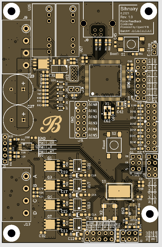
Unfortunately, it does use some exquisite Boutiqe Chips (read as rare and sometimes end of life) which are hard to come by these days, so I started to do my own!
I finallized my Stepper/BLDC Control Board just today. Its based on Openffb and should arrive within the next week. It uses widely available components, supports BLDC and Stepper motors, 2 Encoders and a Braking Resistor (similar to the openffb Board but different ).
The design has a one Axis Controller on the PCB but is stackable for up to 3. The software supports multiaxis as well (since last week ).
Already ordered a hotair soldering station for the TMC Chip.
Ah beautiful! Congratulations, you are quite more ahead than me now
I have received today the encoder, it got stuck for one week in the custom with UPS… my usual luck.
I will need to make a frame with the 3D printer to install it on the motor and then I will start to see how the code works with the encoder.
Good luck with the U1… those thermal pads are nasty. If you still have to manufacture the PCB, I find useful to put some vias on the thermal pad, useful also to spread the heat on the inner/bottom layers, and most of all useful to ensure that the solder paste under the IC is properly melted either by applying hot air on the vias or by warming them with the normal soldering iron.
Do I understand correctly that you connect the encoder directly there and it does everything by itself to implement a servo? Or is it talking only about the hall sensor? Ok ok RTFM would be an appropriated answer in this case, I’m aware of that
Well, lets see first if the PCB works at all or if I have the pleasure to re-do it all over again…
There are adapters for the shaft and mounting it on the motor case… I used double sided tape for the first tests
The manufacturer I bought the motor from kindly sent me the CAD Files for some of the Motor parts (which are actually their manufacturing files) which allowed to replace the motor backshell with a custom design that could fit the motor. However, I decided to wait until I finalized the electronics to see if the motor is suitable at all. Dont want to finalize the mechanics just to realize I could have used smaller motors…
Yes, thats correct. The chip will manage the motor and read the sensors (encoders and hall sensors as well).
If everything works I can send you a few PCBs to test it yourself.
Oh that would be great, thank you.
If it handles everything internally, it’s a really interesting solution. I’m going to give a proper read to that datasheet then, when I saw it the first time it looked to me quite an overkill for this application… but now I have changed my mind!
I have set up my breadboard now to use the encoder, I need to change the configuration on the pic and give it a try, just to see what comes out.
I can see the chip can work in the torque control mode. That’s good. The question is, can the torque be freely controlled when the motor is held still by an external force (pilot’s hand on the yoke)?
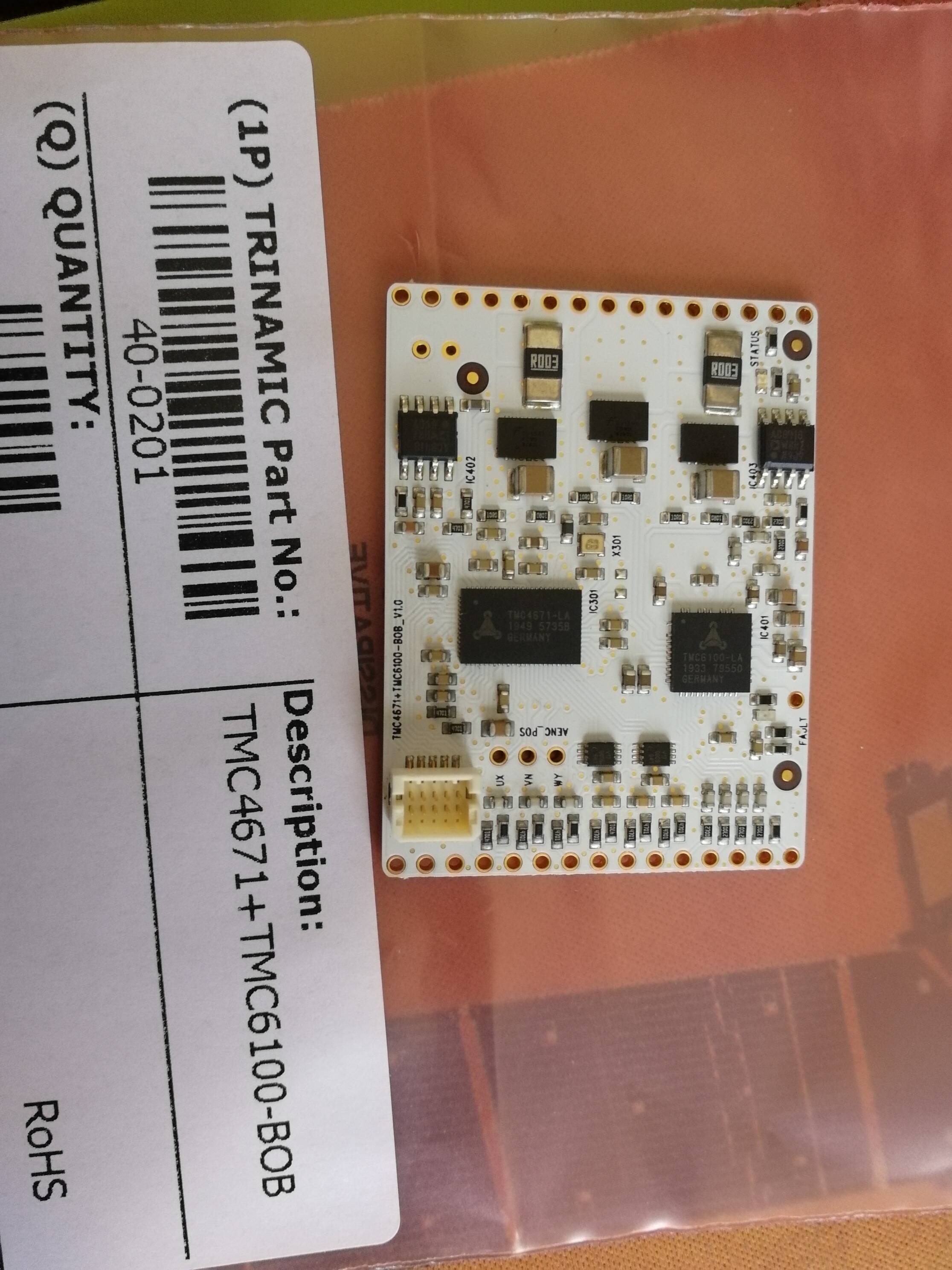
I have ordered the development board (or BOB to be more precise) so I will give it a try.
On another forum they have indicated to me this project:
The videos look really good, it is used also for FFB wheels… and it is for Arduino
I’m looking at the code, passing it from C++ to C won’t be that straighforward, but removing all the general stuff should make the job simpler. Still, I want to try also the other driver.
Are you sure you can solder those packages by hand? I tried a smaller one with the machine I had at work (for BGA) and without a solder mask to apply the paste was impossible. And it was a 16 or 32 pin package. With no exposed contacts you will never know if it’s properly soldered…
Spent the last two days fixing some errors… One thing was/is that the overcurrent circuit differs a bit from the simulations (still have to look into it). The Encoder was not recognized (missed to solder one side of a resistor on the input ) and the current sensing circuit was not working properly (mixed up + and - on the current amplifier so that the voltage output was reduced when current was flowing through resulting in an overcurrent situation…).
But now, it seems to work! Implemented the “virtual” end stops (180° turn).
Hardest part is done, now the testing continues
And a video in which you can see the hard stop function (and my (patent penting) high reliable encoder connector as well). As the first axis is working, I will try to hook it up to the Flight simulator.
Already tried the spring effect… with 0 damping…
The Board also has a few digital and Analog Inputs I will use for Buttons and encoders (trim or flaps maybe).