Help Understanding Piston Engines w/Constant Speed Propellers

I’m not familiar with the islander but I think you were right in this case. As long as you don’t pull the prop lever to feather the prop lever should have little to no effect on an idling engine.

Again not familiar with this aircraft but seems strange to me. I just went through the POH and engine owners manual for the Lycoming O-540 and I can’t find anything that indicates it works any different from other types of engines.

1 Like

I’d had a similar experience. After I was told it was by design, I’d tried to find a reference to it, but couldn’t.

Could I trouble you to take a look at post #49? I’d asked you for some clarification on the turboprop and wondered what your thoughts were.

The whole purpose of the constant speed prop is to achieve a high propulsive efficiency over a wide speed range. A fixed pitch propeller is only efficient over a very small speed range. A fixed pitch propeller optimized for climb will have good performance during take-off and climb but during cruise the blade angle is too low. A fixed pitch propeller optimized for cruise has good cruise performance, but during take-off the blade angle is too big so performance is lower, more runway required, slower climb. The constant speed propeller aims to be efficient over a wide speed range, if the correct speeds and power settings are used this will result in optimal blade angle for the phase of flight and optimal performance.

First of all, forget about the compressor section RPM. Its mostly irrelevant (ok it can be limiting apparently looking at the C208 POH, most aircraft you won’t even look at it during flight), when you want more power from the compressor section you introduce more fuel which makes it spin faster to increase the compression ratio of the compressor and therefore increase the mass flow through the engine (and turbine) which increases the power extracted by the power turbine which is send via a reduction gearbox to the propeller. This is completely separate from the propeller issue. They are unrelated.

Think of the compressor section as a box where a shaft is coming out which drives the propeller via a gearbox. How that power is produced is not very relevant for the propeller system itself. Sure this “box” has limitations which needs to be observed such as ITT and Ng RPM, but they are unrelated to the propeller system itself. As for the reason a turboprop needs a reduction gearbox to drive the propeller, a jet engine produces high RPM but at a very low torque. Its like trying to turn the wheel of your car with the motor of an electrical drill. You can certainly do it, but not directly. You need a reduction gearbox to convert high RPM - low torque into low RPM - high torque.

What you want to achieve is optimum power or optimum efficiency depending on the phase of flight. Regarding optimum power setting:

  • Power = torque x RPM

In other words maximum power is achieved when running 100% torque at 100% RPM. 100% torque at a lower RPM means lower than rated power. So torque is not a direct measurement of power, its an element. When running at 100% torque and 100% RPM the engine is producing its rated power (the Shaft Horse Power - SHP) which is published in the POH. The engine itself is also producing a bit of jet thrust as not all the energy is extracted from the exhaust flow and converted into mechanical energy so the total power output is usually 10% higher than stated.

In short, for take-off, and maybe also for climb you want maximum power = max torque x max. RPM.

For other phases of flight you are likely looking for the highest propulsive efficieny, which means the lowest fuel burn per unit of thrust. A propeller is basically an aerofoil and like a wing the best lift / drag ratio is reached between 2 to 4 degrees angle of attack on the propeller. The angle of attack on a propeller is depending on:

  • RPM
  • TAS
  • Blade angle

If all three are in balance then angle of attack (in cruise for example) will be around 2 - 4 degrees on the propeller. RPM is obviously selected with the RPM lever and automatically maintained by the propeller governor. Blade angle is (indirectly) selected by the power lever. When adding power the propeller tends to spool up, the propeller governor increases the blade angle to maintain RPM. The TAS is what is resulting from the thrust produced and aircraft drag. If all three are in balance the angle of attack is optimal.

According your POH there are three settings, 1900, 1750 and 1600 RPM. It all depends if you prefer speed or economy, one setting might result in a higher TAS but would burn more fuel while another setting would result in a lower TAS but also a lower fuel flow. Remember the following:

  • Power = torque x RPM

So maximum torque / 740C ITT or 101.6% Ng (whichever is limiting) x 1900 RPM will be highest power = highest TAS = highest fuel burn, vice versa for 1600 RPM.

1 Like

Your knowledge of this is absolutely astonishing.
We are so much the better for it!!

1 Like

Thank you, once again. I’ve learned so much here over the last couple of days and your explanations have very much helped me round out much of what I’ve tried to understand on my own.

I’ve never been able to be content doing something because I was told to do it, I really need to have a fundamental understanding of the why. In so doing, that unlocks my ability to achieve an excellence in what I do.

That has been a key throughout my various careers and I’m applying that same wholeheartedness to my flight simming.

I’ve been truly thankful to have “met” people here in this forum with so much understanding of aviation and the sub-topics within.

I love learning — have spent my entire life in the pursuit of it — and I cannot overstate my thanks here, @anon50268670

A post was split to a new topic: [Advanced GUIDE] Constant Speed Propeller System

Ah, the engine failure section explains quite a bit.

It is very interesting to learn that a multi-engine aircraft is more than just another engine or more, but it also incorporates a rethink on the propeller system. That is pretty clever thinking.

I purposely shutdown and feathered an engine on the DC-6 and then brought it back online all according to emergency procedure in the POH. I found that to be a fascinating set of procedures and also very comforting to find the aircraft just plodding along with that engine
/propeller sitting out there stationary.

1 Like

The throttle is the equivalent of the accelerator pedal in a car or truck.
The propeller pitch control is the equivalent of the gear lever.
The engine has a fairly narrow band of speeds that it runs efficiently and effectively. To get the best performance from the engine, the pitch of the prop needs to change to allow the engine to run at its best speed

As you make the prop grab more air in each revolution, you need to supply it with more power to keep it at its optimal speed. That means more throttle.

My car has an auto gearbox. Once warm, it seems to run at around 1400 to 1600 rpm whatever the road speed in the range from 20mph to 80 mph. Only when accelerating hard or going up a steep hill does it speed up: the gearbox computer keeps the engine running where it is happiest.

Yes. None of that which you’ve explained was what I was confused over. I’m professionally familiar with power band, performance characteristics and gearbox gearing setup — in vehicles meant to traverse the road and track, of course! :slightly_smiling_face:

My confusion was brought about because of the differences in instrumentation between a turboprop and a piston engine with a constant speed propeller — primarily what the tachometer (RPM) was telling me.

The other part was my foolishness in not thinking through basic physics — that it’s going to take a massive amount of energy to spin a large propeller through the air when it’s set to a coarse pitch and that is going to drag the engine RPM down accordingly. To my defense, it’s the former point that was helping sew my oversight regarding the physics.

1 Like

I also wanted to thank @NixonRedgrave for the original question and @anon50268670 & co for the answers.

As someone with no mechanical knowledge at all I would not have been able to frame the question but it has covered what I have also been trying to understand at a much more basic level.

I know that I need to read the whole thread two or three more times to even begin to understand the detail but I am now much clearer about the relationship between the throttle and the pitch lever on my Spitfire, Islander and Staggerwing.

Now, if someone could point me towards a tutorial on their relationship to fuel mixture that would complete the set!

Thanks again. :wave::+1:

1 Like

Regarding fuel mixture.

At the most basic level, a petrol burning engine needs a ratio of air to fuel(petrol) for combustion to take place.

The ideal ratio is 14.7:1, which is referred to as the “stoichiometric” air to fuel ratio. So, 14.7kg of air to 1kg of petrol. If you’ve got that ratio, then you’re getting the most out of your fuel burn and complete combustion is taking place.

In a modern petrol-engined that process is being constantly monitored by the electronic fuel injection system via a number of sensors reporting all the necessary variables to achieve that stoichiometric goal. At a most basic level these would include, RPM, coolant temperature, air temperature, the mass of the air flowing into the engine and the quantity of oxygen present in the exhaust stream. All of that is taken into account when calculating how much fuel to inject into the engine to achieve that theoretical perfect burn.

Ok. Rewind a bit technologically. The carburetor is the most rudimentary of devices that can meter air and fuel, mix it together into an emulsion and feed it to an engine. While remarkably effective at its job, it has some major limitations. The biggest one is its inability to be flexible when it comes to a change in air density.

At sea level, the air is far more dense than air at 5000’. If we look at an automobile that is equipped with a carburetor, it will have been setup from the factory to operate at sea level to a few thousand feet above sea level. If the vehicle was ordered for a specific high altitude locale, it could be equipped with a carburetor that was tuned from the factory for the higher altitude environment it was meant to be operated in most of the time.

The parts of the automotive carburetor (known as “jets”) which regulate how much fuel is fed into the air/fuel mixture are fixed and cannot be changed on the fly. If you drive high into the mountains, say 8000’ where the air is significantly less dense than at sea level, the result will be the carburetor will feed too much fuel into the mix and that stoichiometric ratio will falter and the mixture will become too saturated with fuel. The result is the engine runs poorly, and fuel efficiency goes down. Excess unburnt fuel will also prematurely wear the engine as that excess fuel serves as a solvent and it dilutes the oil from the cylinder walls and also makes its way into the engine oil, diluting it as well. This will start to take a toil on other areas of the engine where lubrication is required.

Unlike the automotive application, an airplane equipped with a carburetor has a mixture control that gives the pilot an ability to actually adjust that air/fuel ratio for a variety of altitudes and performance needs.

There is definitely more to this in terms of adjustment and lean conditions and how that affects what we see reflected on various gauges. In supercharged and turbocharged applications there are more things to consider, too.

Take all that in first, though.

The FAA examiner for my multi check ride was a WW2 Lancaster Bomber pilot .He had crossed the border into Canada to join the war effort before Pearl Harbor .In the decades after war he had trained thousands of students and was one of the regions FAA designated examiners .In the 90’s most of the flight schools at the airport had transitioned to either The Bech Duchess or the Piper Seneca for mult training.The FAA sent a young kid to checkoff the old pro .They got into one of the Duchesses and on takeoff the door opened after they landed the young kid signed him off .The next weekend on an exam ride one of the engines quit and could not be restarted on the next week end in a different Duchess when they feathered on of the props it failed to unfeather .I was idiot applicant number 3 after doing 360s ,slow flightt ,turns around a point etc I was lucky to get a straight in pattern entry after one touch and go it was now time a simulated single engine landing as I throttled the right engine back and was about to bring back the right prop his hand shot over and blocked me from bringing back anywhere near feather .I guess even a multi thousand hour pilot can get skidish having been snake bitter the previous 3 weekends.

1 Like

If ya guages go into the red that’s bad you don’t need to know anything else!

https://forums.flightsimulator.com/t/help-understanding-piston-engines-w-constant-speed-propellers/502614/66?u=nijntje91

Brilliant, thank you. Think I have got all that. Not sure where you are but I am in the UK so coming back to this after a night’s sleep and some strong coffee!

Yep, had learned that through hard experience!

Following this thread has left me also wanting to understand a bit more about what is going on.

It has also made me consider quite what is involved in creating a digital simulation of these processes and then making them accurate for different aircraft and conditions, quite apart from the modelling, aerodynamics, weather and everything else it needs to do.

The original post has been moved as “advanced guide” in the student pilot area. To keep a copy here:

I made some highly simplified drawings of the constant speed system.


Constant Speed Propeller System

Diagram:

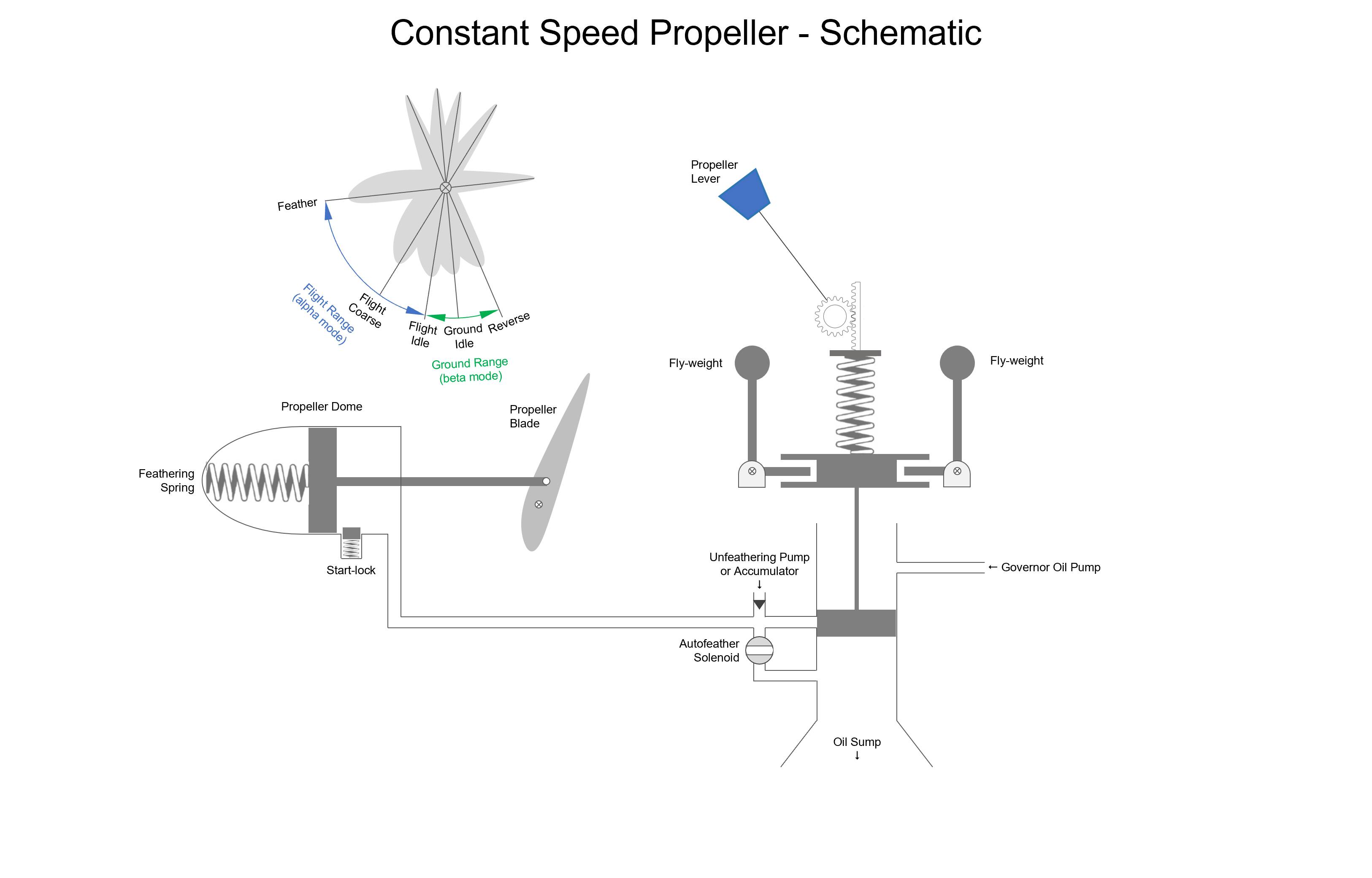
Short explanation of what everything is:

  • Constant Speed Unit (CSU) consists of a valve which modulates oil pressure to and from the propeller dome, this valve is controlled up and down by the balancing act between a spring which is controlled by the propeller lever and two fly weights. Important to understand that those fly-weights are turning around with the engine, they are mounted on top of two “L-shaped” brackets and are able to pivot at the corner of the “L”, thus are able to move the valve up / down. The tension of the spring which holds the fly-weights down is adjusted by the propeller lever.
  • Oil pressure is supplied by a governor oil pump, the hydraulic medium used is engine oil, the same oil used for lubrication of the engine. The oil is usually supplied to the propeller dome via an oil channel in the crankshaft, I tried to keep my schematics as simple as possible so I took some short cuts.
  • A feather solenoid (if auto feather installed) is a valve which is opened (automatically) in case of an engine failure to dump oil pressure and feather the propeller without the need for placing the propeller lever into the feather position. Its not shown on the diagram but placing the propeller lever into the feather position mechanically lifts the valve in the CSU up, essentially bypassing the whole spring and fly-weight system.
  • To unfeather the engine after the engine has been feathered oil pressure is needed. On a free-turbine engine you can simply start-up the engine with the propeller feathered and unfeather as soon as oil pressure is available. On any other type of engine you need to unfeather the propeller in order to start, this is done with an electrical unfeathering pump or a unfeather accumulator which stores oil pressure when the engine is running. The oil pressure is released from the accumulator when moving the propeller lever out of the feather position.
  • The propeller dome houses a feathering spring which pushes on a piston which is mechanically connected to the propeller blades, placing them into the feather position. On the other side of the piston oil pressure is used to press the piston against the feathering springs into fine, and eventually ground idle and reverse positions (if applicable). There is a whole system installed which let the power lever directly control the blade angle when in the beta / ground mode by modulating the oil pressure, but that is for another time maybe.
  • On free turbine engines it doesn’t matter if the propellers are feathered after engine shutdown on ground, on any other type of engine the engine can’t be started with the propeller feathered. Therefore one or more start-locks are installed. The start lock consists of a spring pushing the lock inside the dome to prevent the piston from moving all the way to feather, locking the propeller into a fine position. Centrifugal force flings the lock out when the engine is running, removing the start-lock.

Single engine versus multi-engine

On single engine piston aircraft the propeller system is built so that oil pressure keeps the propeller into a coarse position, whenever oil pressure is lost the propeller moves to full fine so the propeller will “windmill”. On a single engine aircraft the priority is to keep the engine running to perform a restart.

On a multi engine aircraft the priority is to remove the drag and continue flight on the remaining engine, therefore the propeller system is designed to go to the feathered position whenever oil pressure is lost, oil pressure is used to keep the propeller in fine pitch in flight.

Also on free-turbine engines you don’t want to have the propeller windmilling as it only creates drag and doesn’t turn the engine itself for a restart. The TBM and C208 for example feather when oil pressure is lost.

All the diagrams below are for a multi-engine / free-turbine engine aircraft (oil pressure = fine pitch, lack of oil pressure = coarse pitch and eventually feather). For single engine aircraft the principles remain the same but its working opposite (oil pressure is coarse pitch, lack of oil pressure is fine pitch).
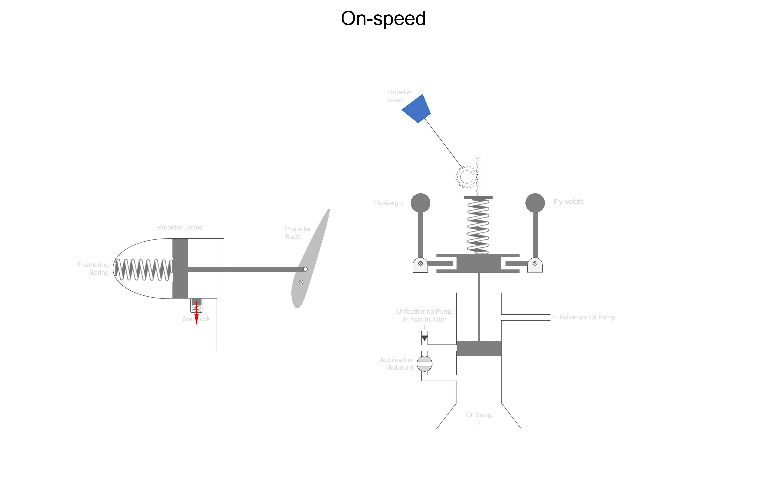

On-speed

Below the on-speed condition. The propeller is running at the selected speed, the piston blocks oil from going into, or moving out of the propeller dome, creating a “hydraulic lock”.
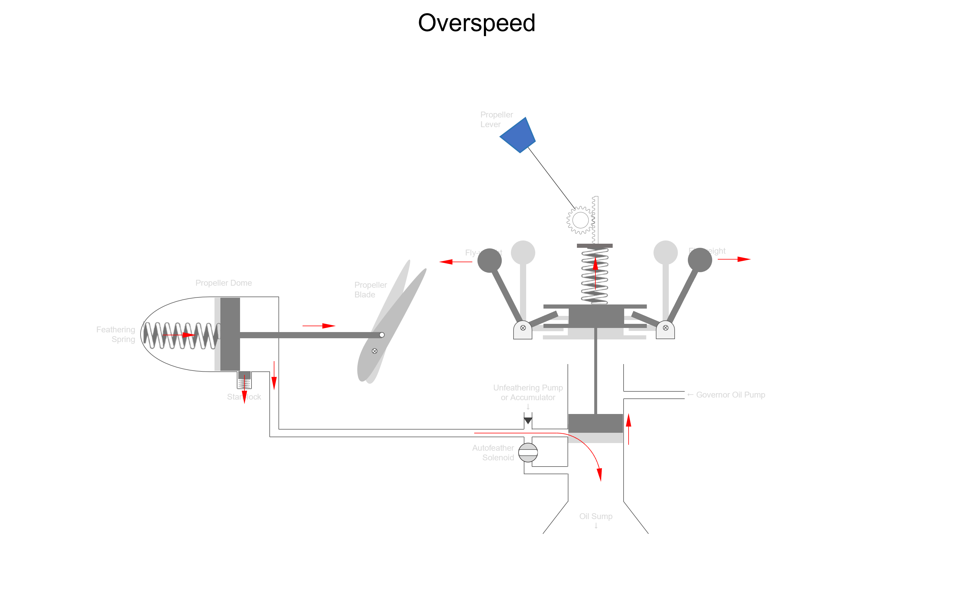

Overspeed

When the propeller is rotating faster than the selected RPM the fly-weights are flung out by centrifugal force and pull the piston up to dump oil pressure from the propeller dome. As oil pressure in the propeller dome decreases, the feathering springs push the propeller into coarse pitch. Coarse pitch means the propeller takes a larger bite of air, producing more thrust, also creating more load on the engine. The propeller RPM drops back to the selected RPM and we are back “on-speed” as in the first picture.

Examples of when this happens:

  • Adding power (moving power lever forward)
  • Increasing speed, for example starting a descent without reducing power
  • Selecting a lower RPM (moving RPM lever back)
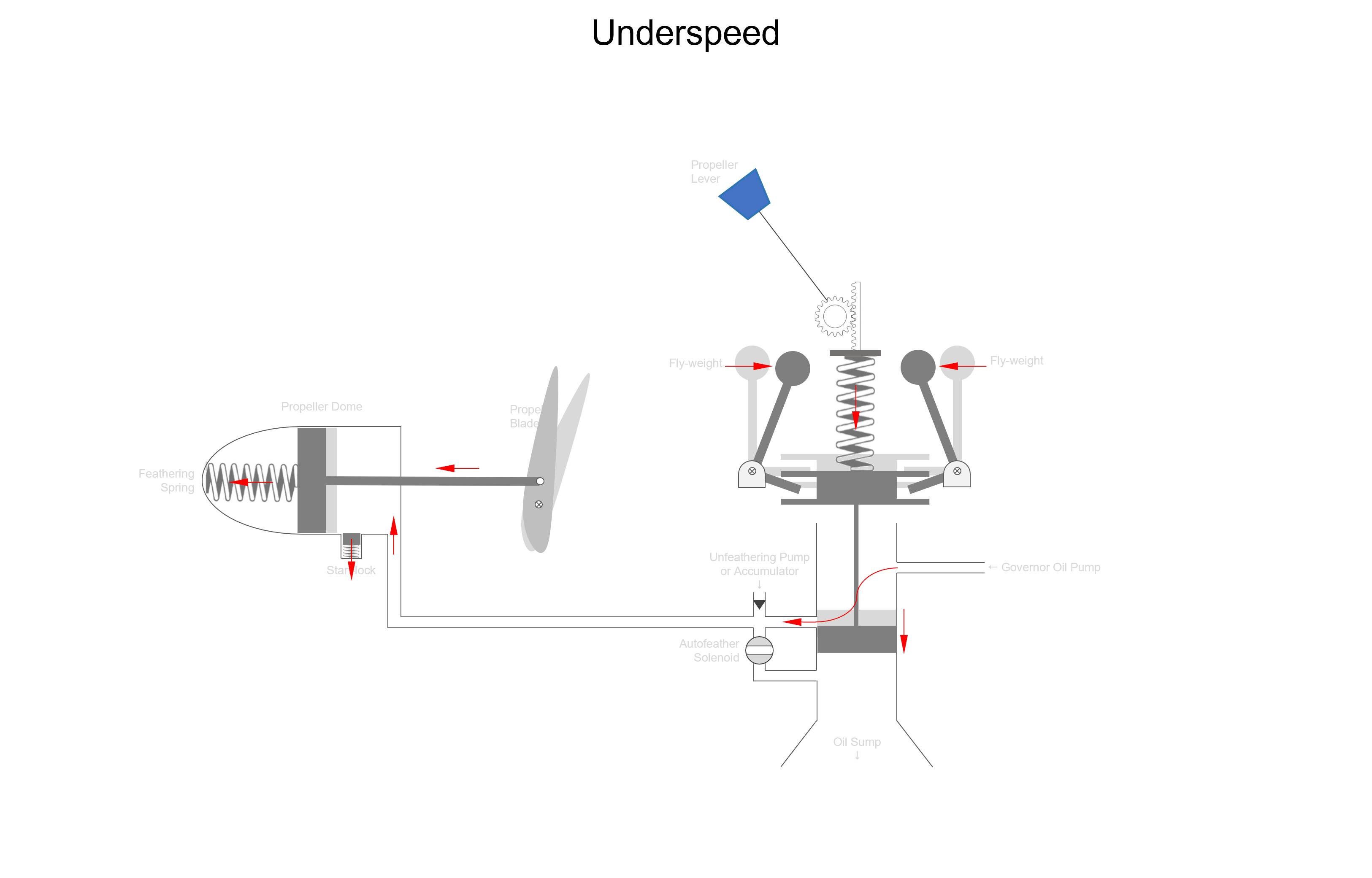

Underspeed

When the propeller is rotating slower than the selected RPM, the spring is able to push the valve down against the fly-weights due to the lack of centrifugal force. Oil from the governor pump can now enter the propeller dome and move the piston in the propeller dome against the feathering springs to the left, placing the propeller blades into fine pitch. Fine pitch means the propeller is taking a smaller bite of air, thrust reduces and load on the engine reduces. The engine RPM spools back up to the selected value and we return to an “on-speed” condition as in picture one.

Examples of when this happens:

  • Reducing power (moving power lever back)
  • Reducing speed, for example starting a climb without adding power
  • Selecting a higher RPM (moving RPM lever forward)


Engine failure

As explained before, when oil pressure is lost a multi-engine / free turbine propeller system, the propeller will feather. This might sound like the propeller will automatically feather upon an engine failure, this is not true! As the engine fails, RPM drops and this is sensed as an underspeed by the propeller governor, consequently the propeller is brought into fine pitch. In fine pitch the engine will windmill and as long as the engine windmills the governor pump is running, as long as the governor pump is running there is oil pressure available to hold the propeller in fine pitch. So you either need an autofeather system which automatically feathers the propeller or otherwise manually pull the propeller lever into the feathering range to dump oil pressure and bring the propeller to a stop.

3 Likes

I really appreciate you sharing your vast stores of knowledge with us, it’s really great! Thanks a lot.

One of the difficulties with this topic is that often the explanations are all about ‘how’ it works and not ‘why’. It’s amazing ‘how’ it’s made to work, for sure, but for me the problem is ‘why’. Reading the explanations of the governor (etc) is good, but not helpful to understand the ‘why’. I guess I should read this thread more closely and work out the ‘why’ or are there any articles out there that would help? I fly the JF Piper Arrow III in the sim, which has a constant speed prop so I need to know the ‘why’ !!

If you scroll a bit back in this thread:

1 Like