This topic is in the process of filling as there’s no draft feature in MSFS forums, so please be patient!
Okay, this is clearly inspired and is similar to @mixMugz’s topic on making unmirrored liveries using Blender, but hear me out:
After Asobo introduced submodel merging into the SDK last year, the process of making mesh liveries became much, much easier than before. With this method, you don’t need to fumble with JSON scripts and such. Albeit you would end up using the in-game SDK to compile the GLTF files so MSFS could read them.
The process in making these kinds of liveries is almost identical to Mugz’ method, so you can follow the steps they made before they get into the animations:
Trust me - you won’t need to fumble with animations in this one. But please, read the original topic so you can be well-versed in the basics of making mesh liveries in Blender first before coming here.
You ready? Let’s get into it.
First of all, the prerequisites. They are identically similar to Mugz’, albeit with several key differences:
- Blender. We’re going to use BOTH Blender 2.92+ (I’m using Blender 2.93) and Blender 3.3 LTS . Install them separately with either one using Steam and one downloaded from the official website, or just download both from the official website then install them separately. We’ll get to that.
- FlyByWire GLTF plugin [GitHub - flybywiresim/msfs2blender2msfs: Fork of the official Blender glTF 2.0 importer and exporter designed for MSFS 2020], install this for your Blender 2.92/93 installation.
- Official Asobo GLTF plugin [GitHub - AsoboStudio/glTF-Blender-IO-MSFS], install this for your Blender 3.3 LTS installation ONLY.
- Photoshop, Paint.NET , Gimp any graphics editor for creating textures. We’ll need at least one additional texture with decals and color for our liveries.
- VisualStudio Code, Notepad ++, Notepad - or in general any text editor. We will have to modify the GLTF files. By their structure, they are a regular JSON file. And it is desirable to have an editor with a validator and ease of editing.
- And again, like Mugz said, patience and mindfulness. We’re gonna need a lot of it this time as well.
Now then. The first steps in making this is pretty much similar to Mugz’ existing topic. You will need to install the FBW plugin complete with its prerequisites (texconv.exe and such), in your Blender 2.92/93 installation.
Secondly, you will need a second Blender installation, which is the 3.3 LTS version. The latter will be used to configure the materials as well as exporting the decals you’ve made with Asobo unique ID credentials. I’ll explain this later on.
For this demonstration, we’ll be using the Asobo/Microsoft/Hans Hartmann ATR 72-600 for this project. I picked this because this is one of the very first MSFS aircraft to use submodel merging for its liveries.
Before we start, we definitely need to import the model into Blender first. Like Mugz recommended, I also recommend LOD00 models first and foremost, or else there will be artifacts in your mesh livery. However, since the Asobo ATR has its LOD00 model encrypted, I suggest downloading this particular paintkit which, for some reason, has the LOD00 model.
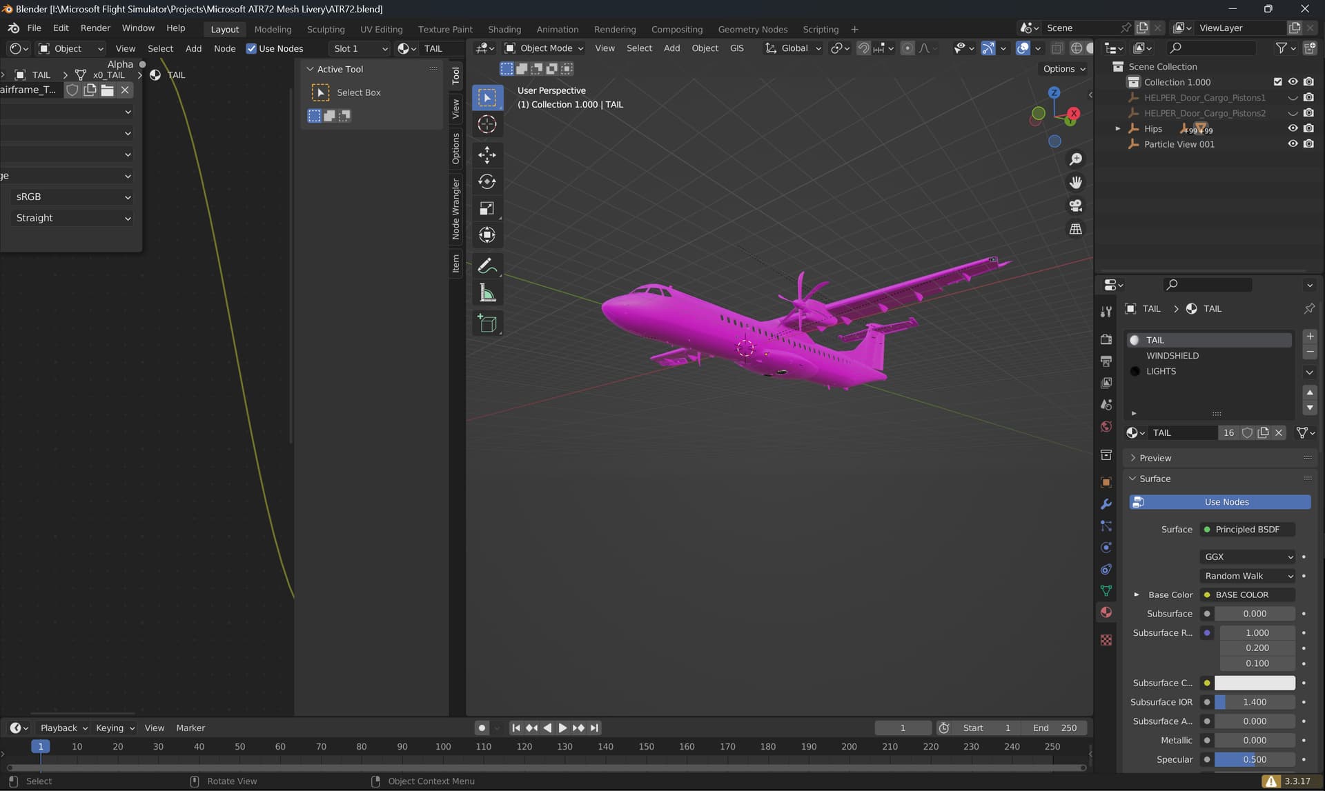
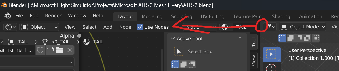
Opening the Blender file from the paintkit, you’ll be greeted by this. Don’t worry, you can fix the layout by dragging the empty space highlighted to the left:
Now, you can go to the outliner and press the eye button next to the “Hips” object while holding Shift twice. This will bring up the aforementioned “hips”, which we will need for later.
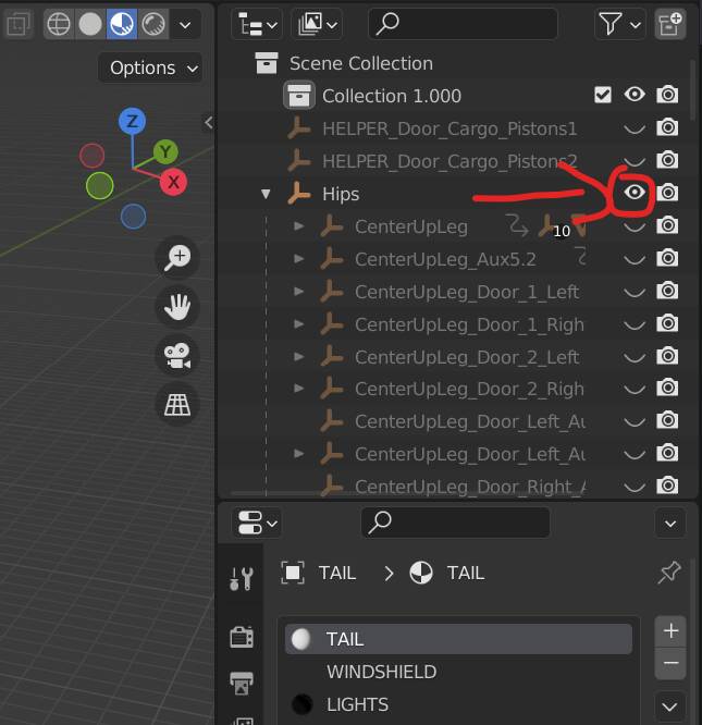
With the “Hips” visible, your model will now look like this:
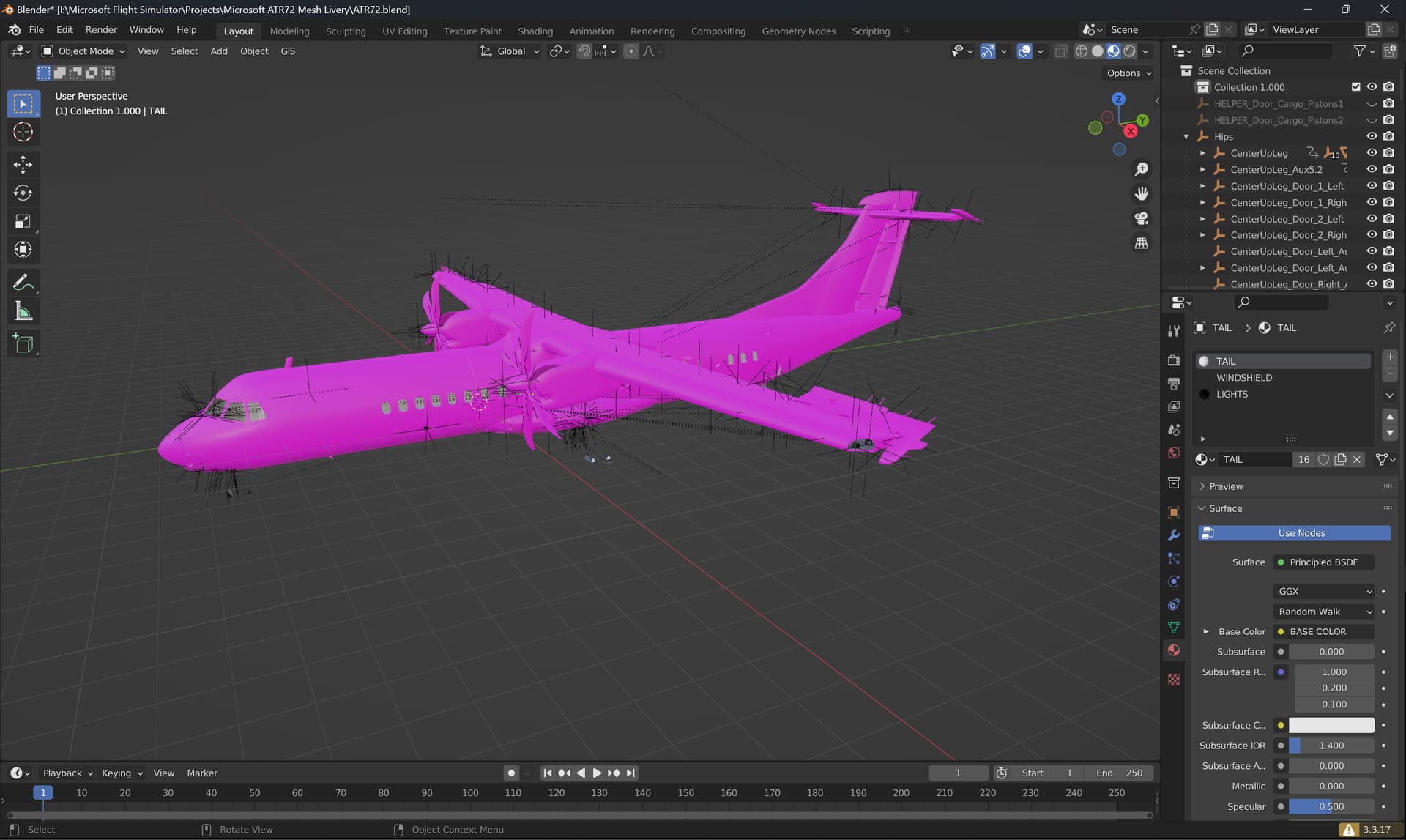
The next process, while sounding counter-intuitive, is to delete ALL animations while centering the rudder. This process will be a bit tedious, so bear with me. With submodel merging, all we need is the aforementioned “Hips”, which will be used by the simulator to reference which models are moving with which parts in-game.
Also, newer models tend to have nonlinear animations (NLA) for the rudder (and most flight control surfaces) that are locked to 1.6 frames, instead of the usual 81 frames found in older Asobo models. This makes the process of centering the rudder and other flight control surfaces much more difficult than before. However, it still can be done.
First of all, much like in Mugz’ tutorial, what we need to do is to first go to the Animation tab, then selecting “Nonlinear animation” in the bottom tab.
You will be greeted by unusual NLA tracks that stopped halfway before entering the second frame:
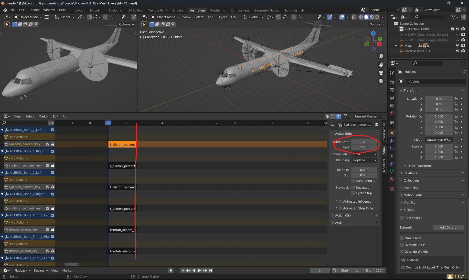
As you can see, most NLA for the flight control surfaces are now just 1.6 frames long, starting from Frame 1 and ending up at Frame 2.6. What we need for now is the rudder as we will be painting over it for most of the time. The method that I’m going to give you is also applicable to other flight control surfaces if you wish to paint them as well, but let’s focus on the rudder first.
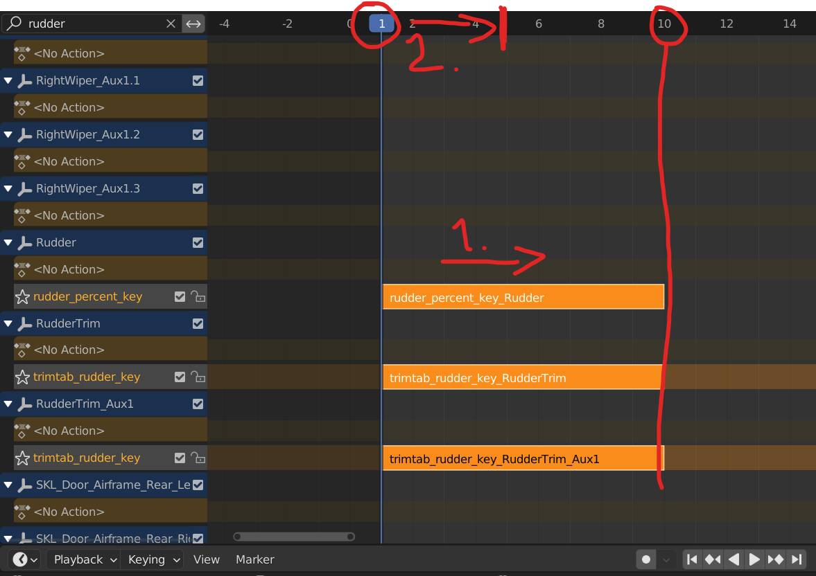
First, go to the search bar and type “rudder”. This will bring you 3 NLA tracks that you can tinker with.
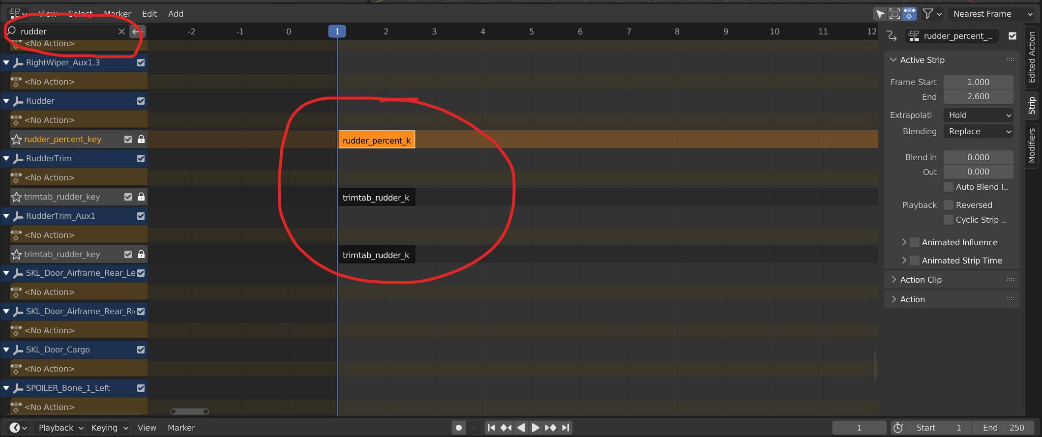
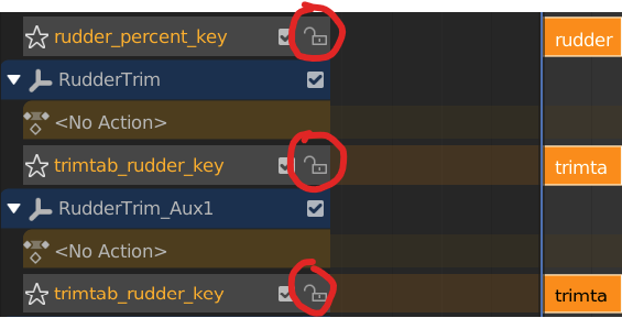
Next, we can unlock the three NLA tracks here by pressing the lock button.
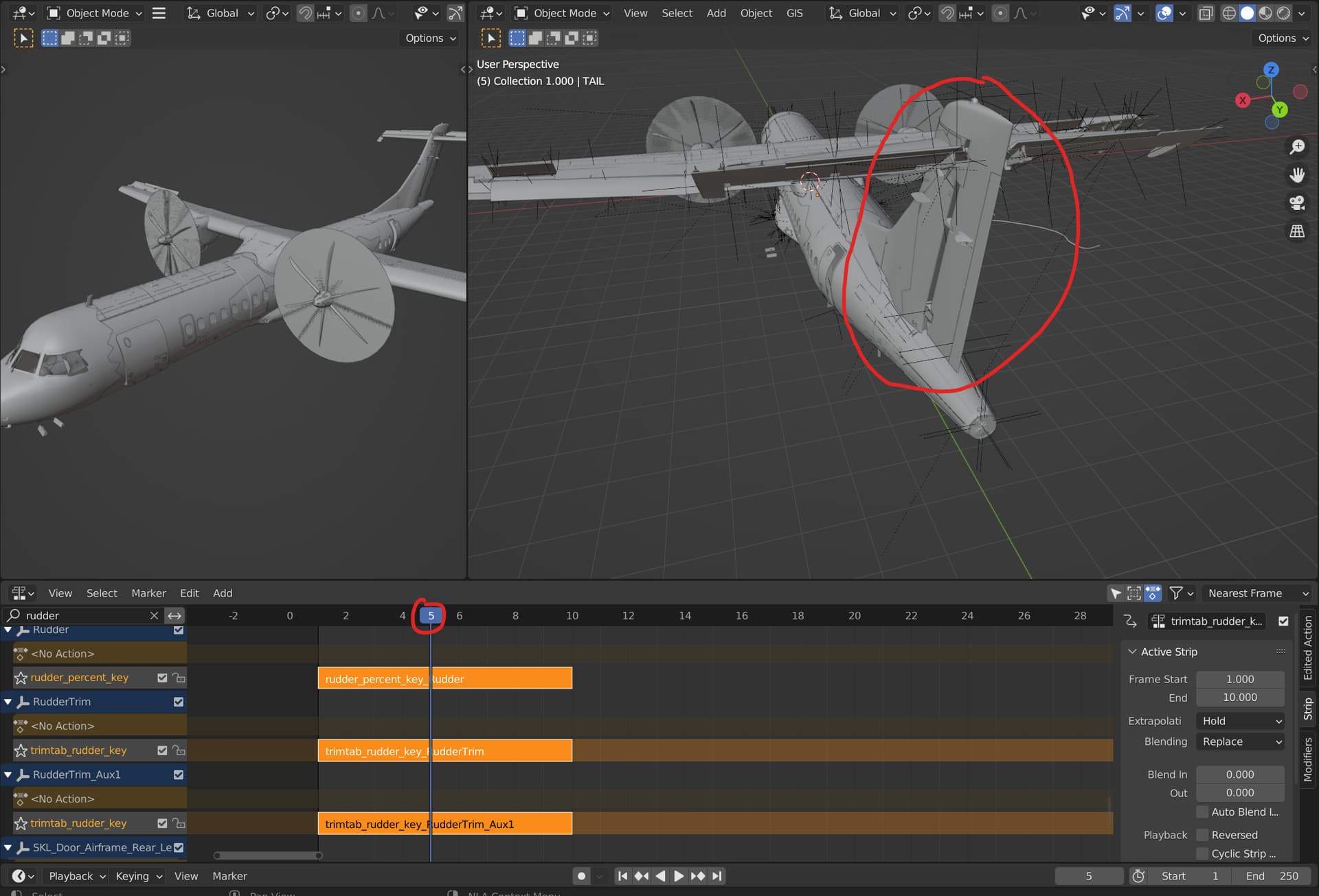
Then, while keeping the timeline slider at Frame 1, select the three NLA tracks and press “S” to scale the NLA tracks up to 10 frames. Afterwards, slide the timeline slider to Frame 5 to center all of the rudder control system, including the trim tabs.
The animation may look jittery and incomprehensible when you slide the timeline slider, but don’t worry. With this configuration, Frame 5 is where all the rudder control surfaces are centered, as seen here:
Afterwards, hover your mouse to the nonlinear animations section, then press X on the keyboard to delete the NLA tracks. This will delete the animations for the rudder and make the process of painting the tail rudder much easier and accurate. This process can be used to center other flight control surfaces if you wish to do them all. However, it can be a work of trial-and-error when it comes to centering other flight control surfaces as some may have differing centered frames.
Do not worry about the deleted animations, as we don’t need to bake any animation with the submodel merging method. All we need are the “skeletons” (or “Hips”) which are represented by the plus-looking strings in the viewmodel.
After the rudder is centered, you can continue making your mesh livery using the methods Mugz have outlined in their previous tutorial. Below is the link back to the topic so you don’t have to scroll up again:
Done? Ok. Now here comes the interesting part. You should be on Blender 3.3 LTS at this point. Or, if you haven’t, you can just save everything you’ve worked on, and load it into 3.3 LTS now. This is important because the official Asobo plugin is only compatible with that version. And, you simply cannot have both the FlyByWire and Asobo plugin in the same installation as it will conflict with each other, given their exactly similar plugin names (io_scene_gltf2_msfs).
There are several things that makes the Asobo plugin important in this particular method:
- Materials. The Asobo plugin gives you more control in how you want the material to look like using Blender instead of editing the GLTF files themselves.
- Asobo Unique ID. The FlyByWire plugin does not have the feature to input the Asobo_UNIQUE_ID credentials to the MSFS GLTF file you’re about to export. This is one key component in order for submodel merging to work properly.
Before we get into this, we need to link the decals on animated parts onto its aforementioned “skeletons”. Remember the plus-shaped strings I talked about? Here’s the part where it becomes important. This is where the simulator could read that a particular mesh is linked to a skeleton, so that it moves with the intended parts.
Firstly, you realize that there are many skeleton objects that comes with the imported model. Don’t worry, you can just copy and paste the skeleton objects that you want to use by selecting them individually and then pasting them into a different collection.
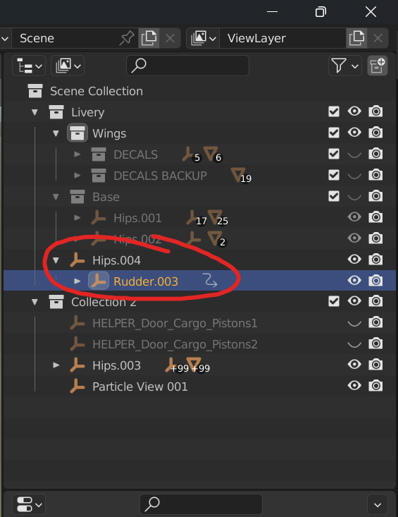
Afterwards, you can just rename the skeleton nodes by removing the numbers corresponding to it, and then we can move on to the next process.
All said and done, then all you need to do is to select a particular decal mesh you’ve made, for example, the rudder, and then parent it to the Rudder skeleton using Ctrl + P.
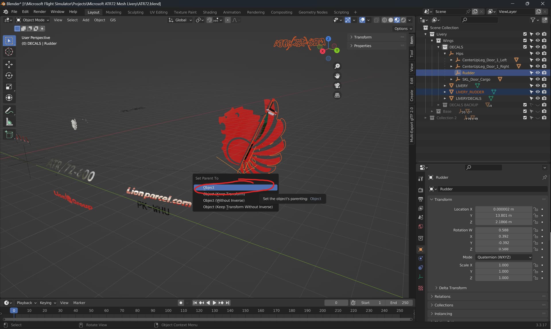
Make sure to select the decal object first before selecting the skeleton so the decal is properly parented to said skeleton to begin with.
Then there you have it! The decal is now parented to the proper skeleton and the simulator will move the decal with the corresponding skeleton node.
Applying the materials is quite straightforward, albeit with extra steps given how convoluted the Asobo shader materials have become, even for myself. First thing first though, what you need to do is to make a new material, and then scroll down until you found the tab “MSFS Material Params”.
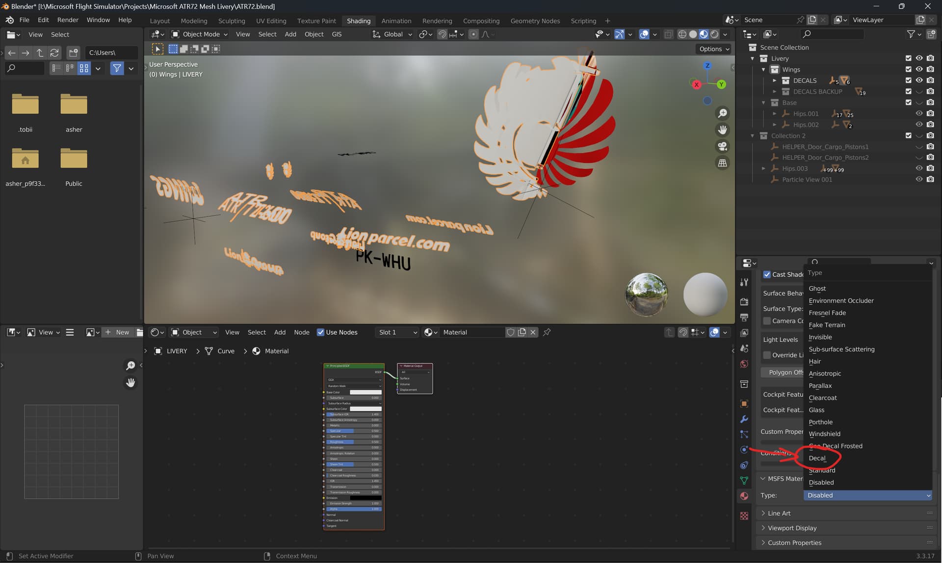
Afterwards, select “Decal” on the drop-down (or drop-up) Type menu. Then, you’ll be greeted with this:
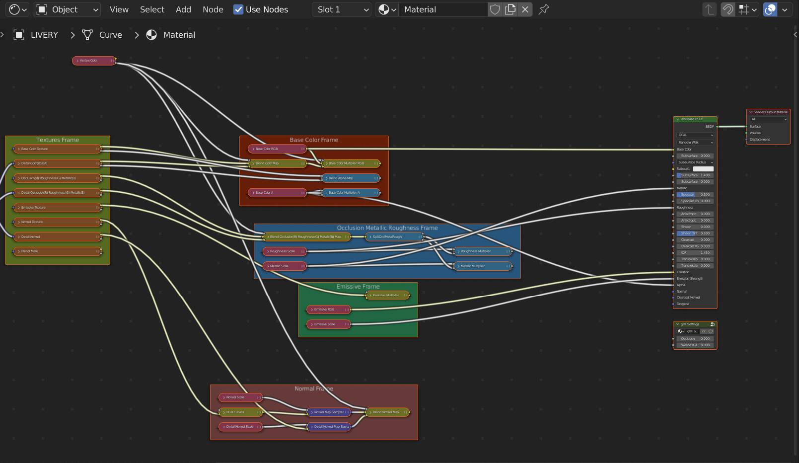
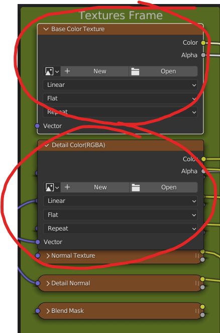
It looks convoluted, because it is. But - don’t worry! All we need to do is to just assign both the Base Color and Detail Color textures with the decal textures you’ve made from Mugz’ tutorial to begin with.
After you’ve selected the textures, what you need to do next is to connect the “Base Color Multiplier RGB” node into the Base Color node in the Principled BSDF shader, and then the “Blend Alpha Map” node into the Alpha node in the Principled BSDF shader.
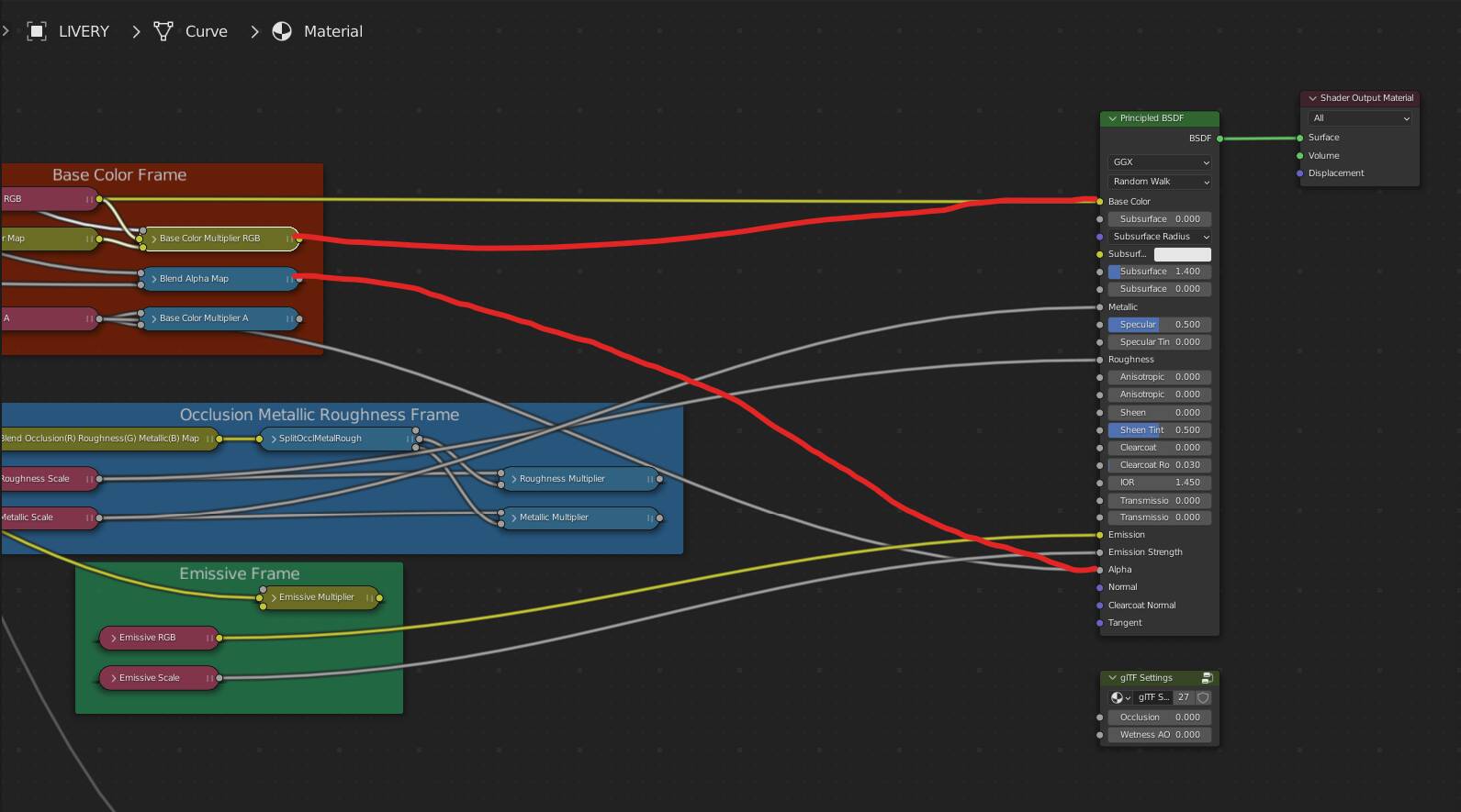
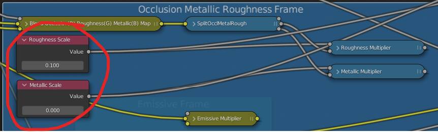
This will replace the existing nodes that was connected to a base color. We don’t need them. Then, you can adjust the Roughness and Metallic scale using these sliders in the Occlusion Metallic Roughness Frame. I usually go with the Roughness value of 0.1 and Metallic value of 0. To make your decals look less glossy (more matte), adjust the Roughness scale. To make your decals look more metallic-looking, you can adjust the Metallic scale.
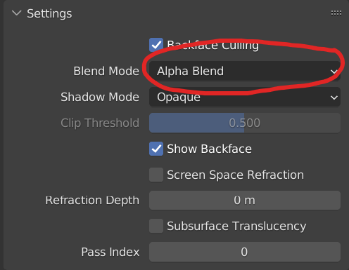
Also do not forget to set the blend mode in material settings to “Alpha Blend” so the transparent decals show up properly:
Then there you have it! The materials are set, and now we will move on to the process of creating a new SDK project for compiling the model to MSFS, exporting the mesh livery, and compiling said livery for use in MSFS afterwards.
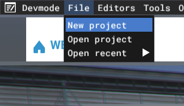
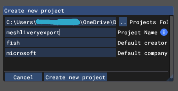
Next thing to do is to launch MSFS, enable Developer Mode, and make a new project by going to File > New Project.
Next, name your project however you wish. In this case, I’m going with “meshliveryexport”.
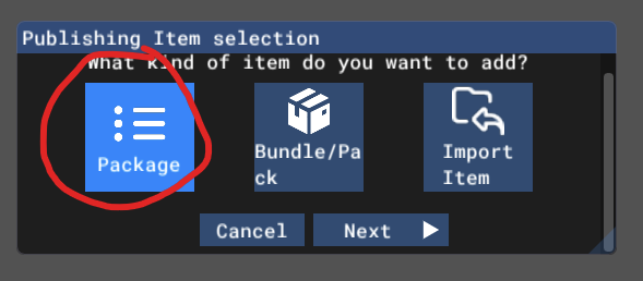
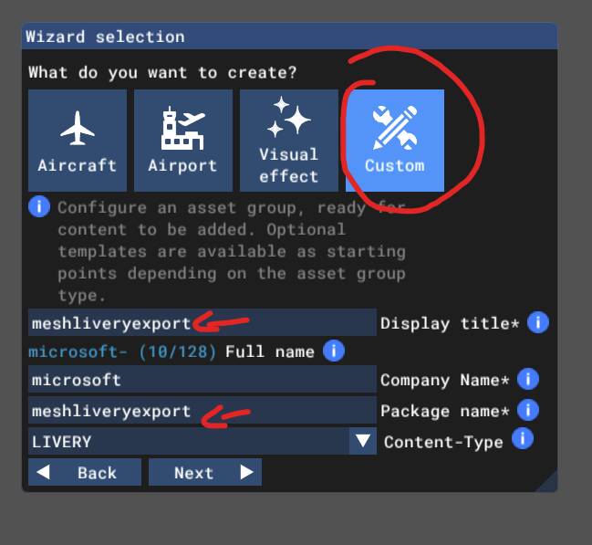
Then, select “Package” in the publishing item selection menu, then press the “Next” button. Afterwards, select “Custom” in the wizard selection menu, and input the name of the package itself on the display title and package name sections.
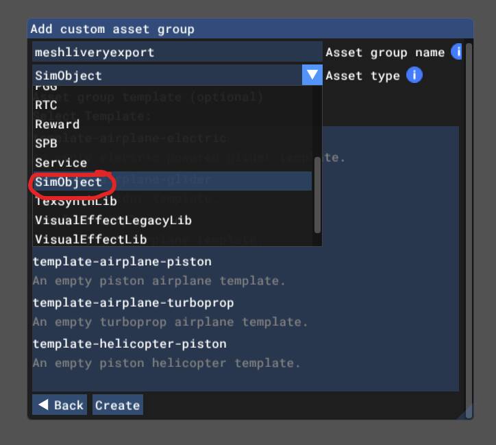
In the “Add custom asset group” menu, select “SimObject” in the drop-down menu, then select whichever template you want to choose. In this case, I go with the turboprop template. Don’t forget to also type in the asset group name. Then click on the “Create” button.
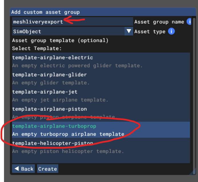
You will be presented with a window below:
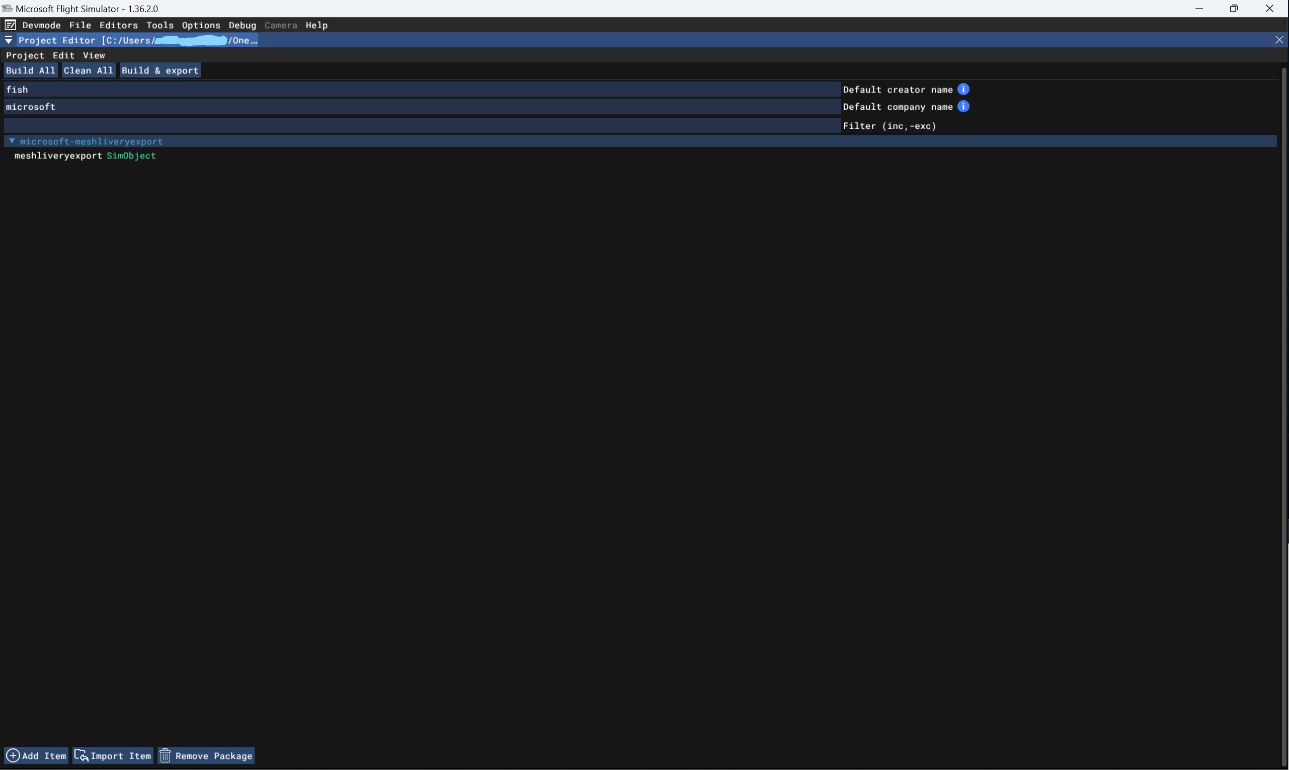
This will include one of the two options on how you can compile the models and textures. But for now, let’s go back to Blender and export what we’ve already made.
Exporting is pretty straightforward, but you might wanna watch some steps here carefully. First of all, you can use the usual method of creating a new .blend file, and copy everything you’ve worked on (excluding the base models!) for the mesh livery into it.
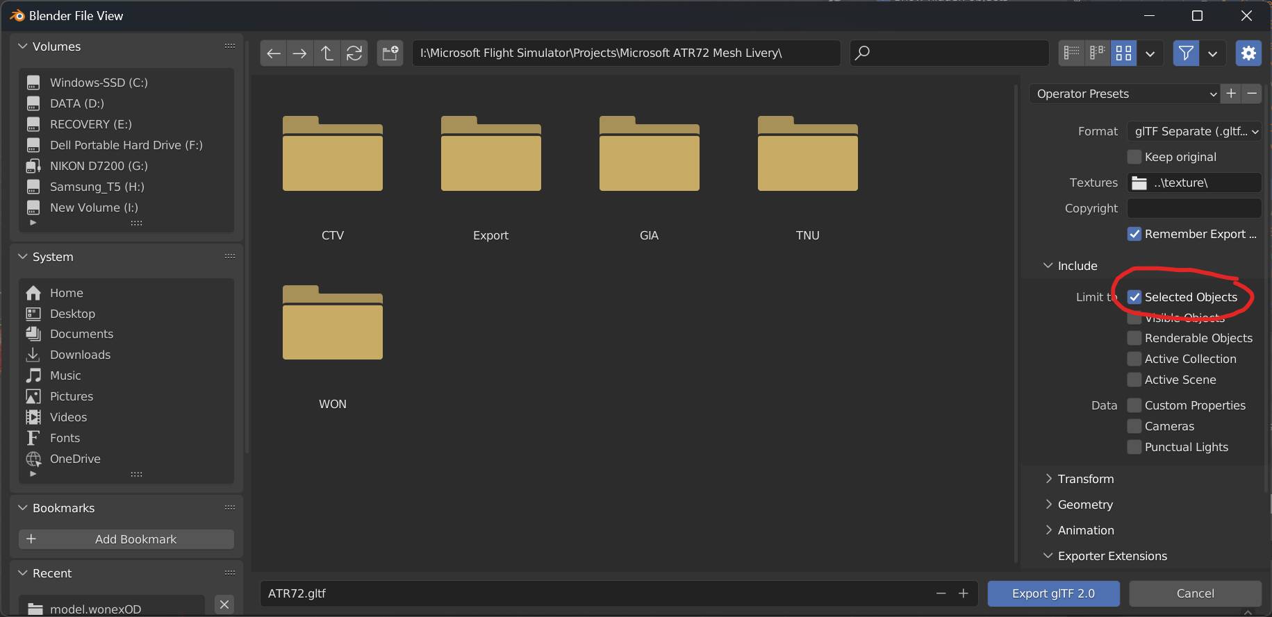
Another way, which I use most frequently, is to hide all the base models in a separate collection, leaving only the necessary skeletons and the livery decals I wish to export, then selecting them all using the A key on the keyboard before going to the File > Export > glTF 2.0 (.glb/gltf). This involves enabling the “Limit to Selected Objects” option under the “Include” menu.
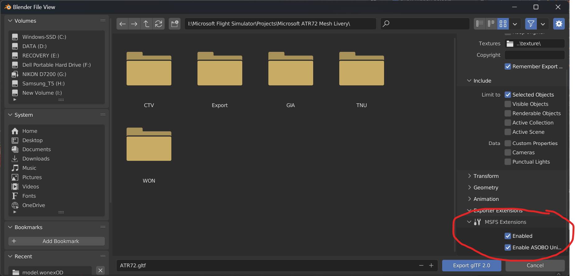
While we’re at it, don’t forget to scroll down and go to the “Exporter extensions” drop-down menu and make sure the MSFS Extension is Enabled as well as the Enable Asobo Unique Id option.
Don’t forget to set the format to glTF Separate. You can either export the glTF object wherever you please, and copy and paste them into the newly built MSFS project folder. However, I chose the much more simpler approach of exporting the glTF objects directly into the MSFS project directory. To do this, simply navigate to where your MSFS SDK projects are usually saved. In my case, it is saved in my Documents folder under the “MyFSProjects” directory.

Navigate down to the newly built project folder, in this case it is named “meshliveryexport”. Go down to PackageSources > SimObjects > Airplanes > [YOURASSETNAME]. There you can find this folder structure:
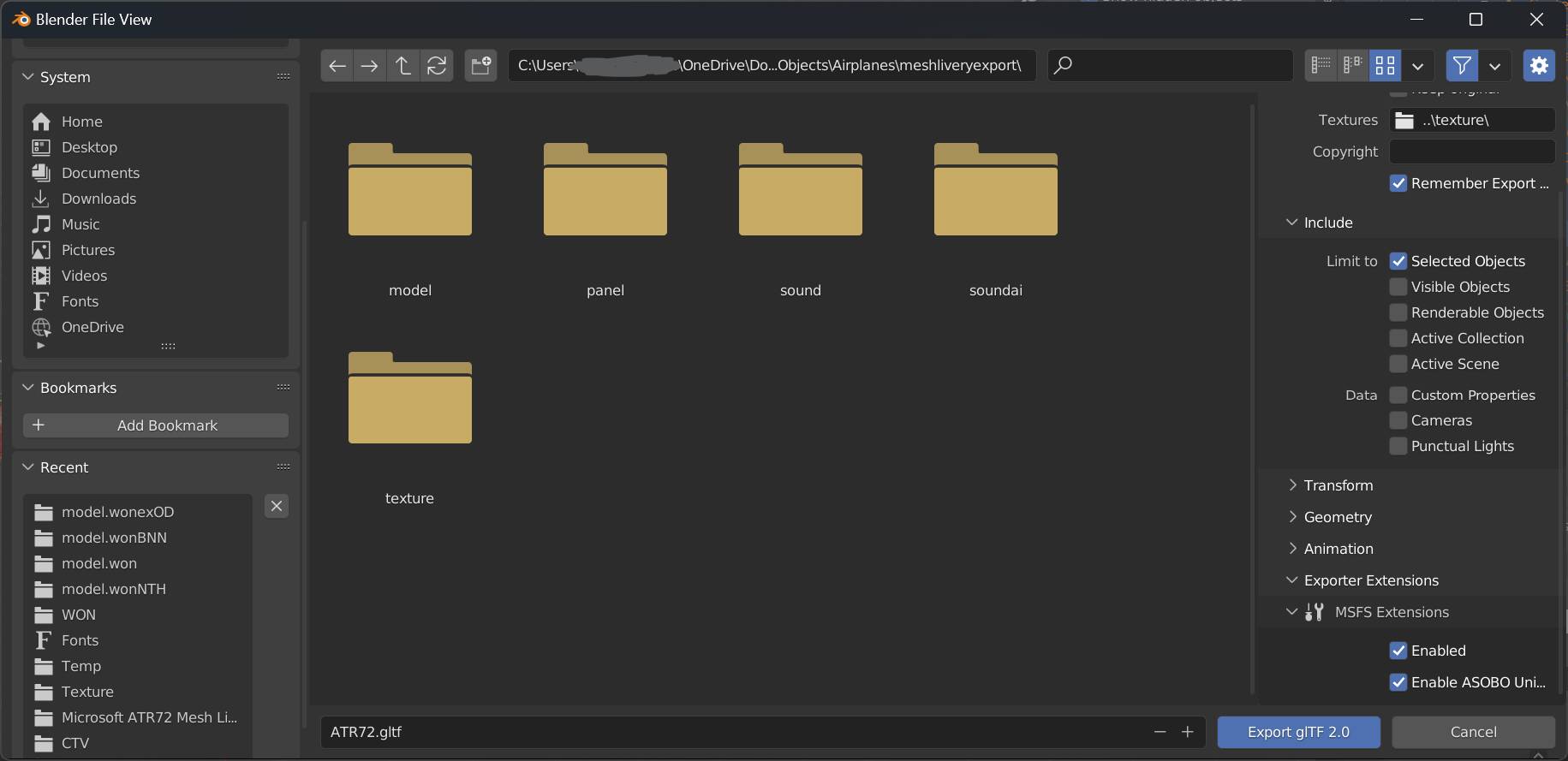
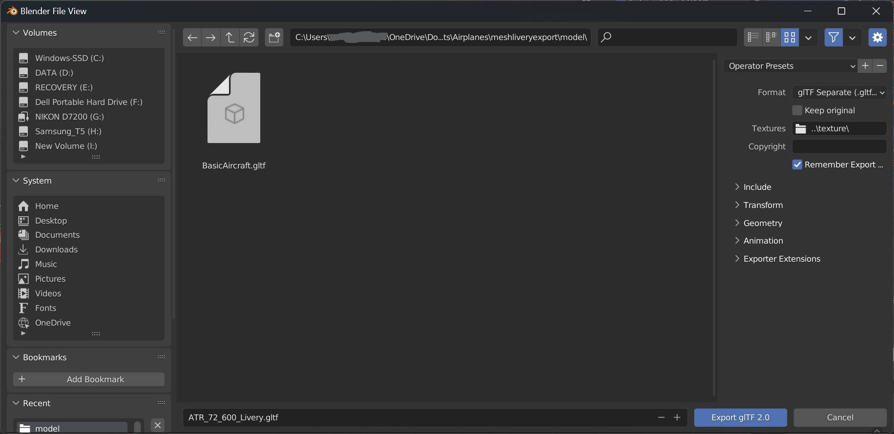
The export location for the glTF model should be the “model” folder, and don’t forget to set the texture directory in the “Textures” tab with a folder icon beside it. Enter the value of ..\texture\ to export the packed textures into the project source’s “texture” folder. This will simplify the compiling process without having to copy and paste them again and again if there are any changes.
For exporting the model, you can either replace the “BasicAircraft.gltf” file, or use a custom name on your own. The former is much simpler, while the latter requires you to edit the “BasicAircraft.xml” file using Notepad++ (recommended) or other text editing software. In my case, I will name my glTF file as “ATR_72_600_Livery.gltf”.
If you choose to name the model differently, all you need to do is to navigate to the aforementioned directory in Explorer, open the BasicAircraft.xml file using a text editor, and then rename BasicAircraft.gltf in the ModelFile line.
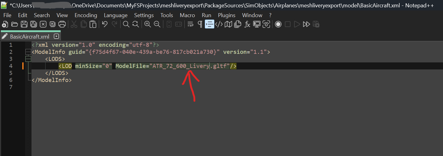
Save the .xml file, and then proceed to compiling the .gltf models for merging.
There are two ways to compile the .gltf model. First, is to do it in-game. It was my primary method for compiling my custom objects for quite a while. Second is to do it outside of the sim using the FS Package Tool executable found in your MSFS SDK installation.
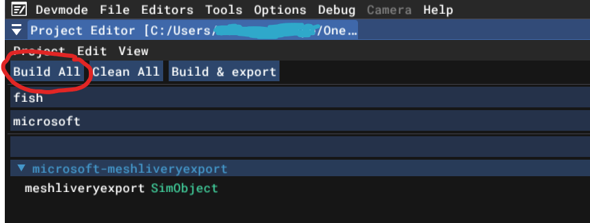
First, let’s explore the in-game method. Remember the SDK window I showed earlier? You can go back to it now if you have your sim still running at this point. However, if at some point you closed the sim, you can always go back to the project by going to File > Open recent > Your project name.
Next is to just press the “Build All” button to compile the .gltf models and the textures from .png to .dds format.
Wait for a few minutes until the compiling process is finished. Then, you will be greeted by a console window telling you if the compiling process is successful or not.
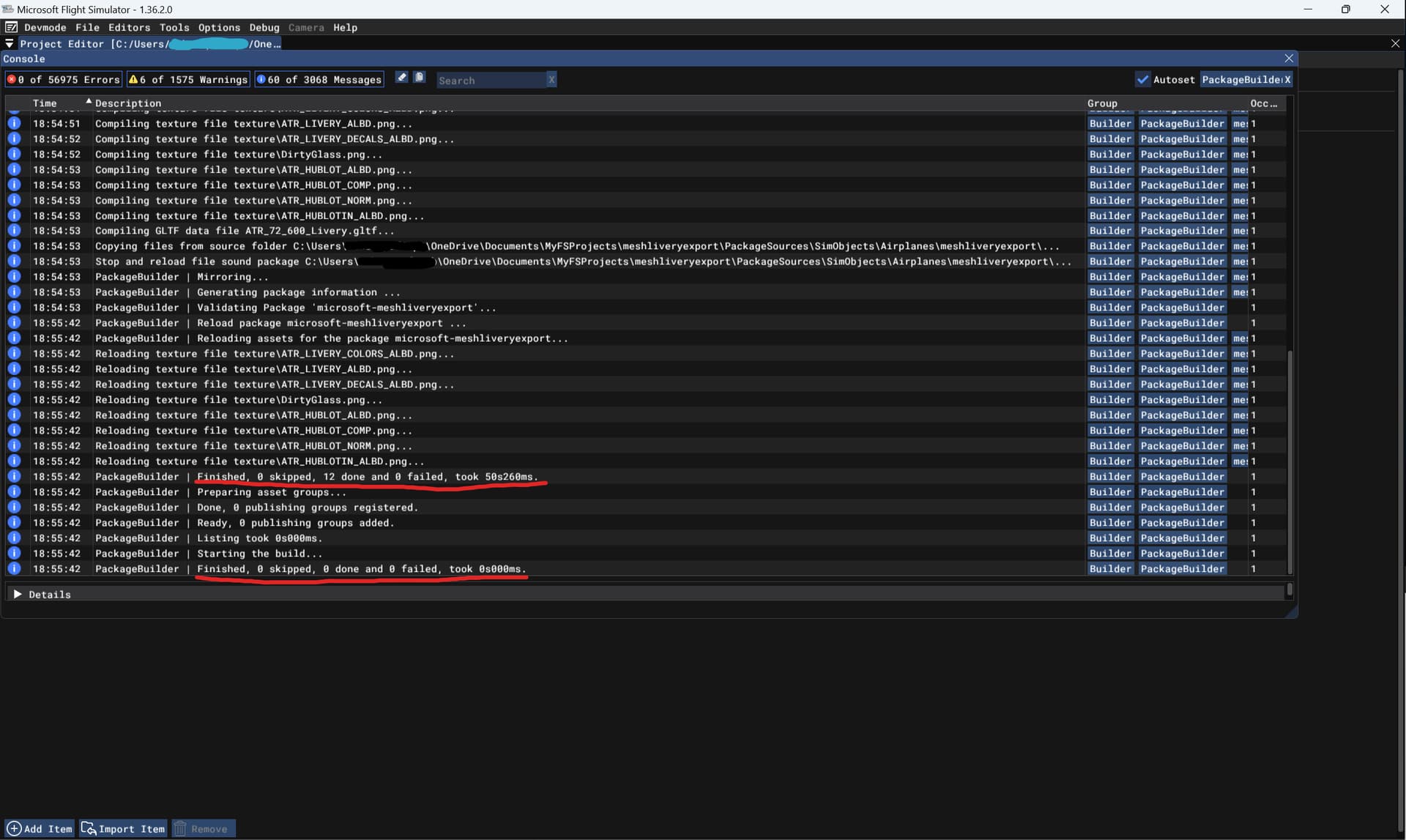
A successful export would have the results like above. Make sure that there are no files that were either skipped nor failed to build.
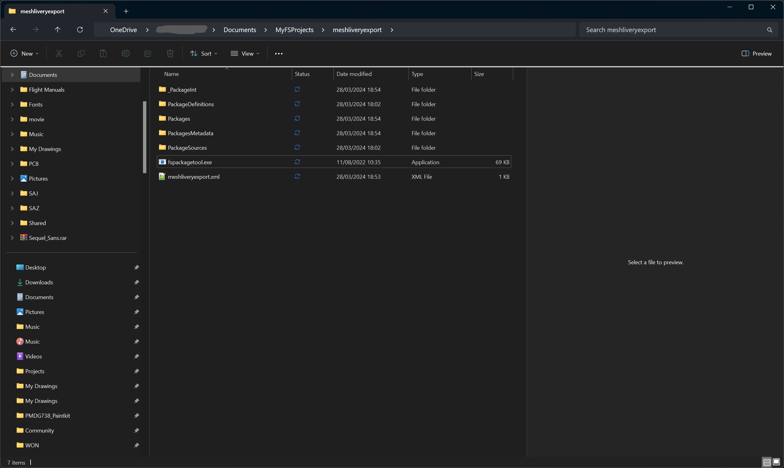
The second method for compiling the objects externally without starting the sim. To do this, you need to first copy the “fspackagetool.exe” executable from your MSFS SDK installation (usually under MSFS SDK\Tools\bin), into your root project folder. The layout of your main project folder should look like this:
At this point, you can just simply drag and drop the .xml file present in the project folder into the executable.
HOWEVER, to make things easier if you have changes later down the line to the model, you need to add launch parameters to the executable. Otherwise, the executable will fail to regenerate the package given there are existing project files already compiled in the “Packages” folder. You can circumvent this by emptying the “Packages” folder each time you want to compile, but that can be too cumbersome.
So, to do this, simply right click and drag fspackagetool.exe, and drop it in the same folder. Then choose “Create shortcut”.
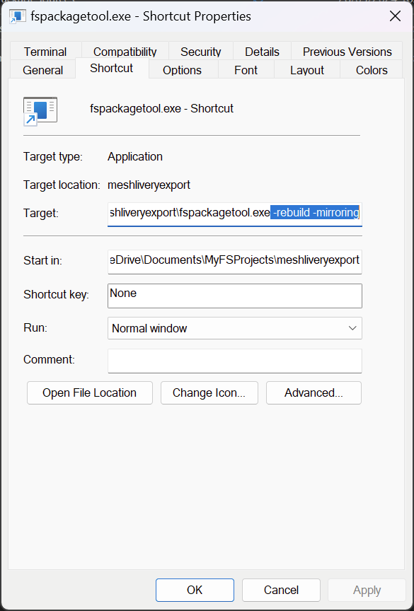
Now, you can add launch parameters to the executable by opening the Properties of the shortcut, and adding to the “Target” box the parameters down below:
-rebuild -mirroring
The correct launch parameters in the “Target” box should look like down here:
Click OK, and then proceed to drag and drop the .xml file into the shortcut.
NOTE: Make sure to close ANY instances of MSFS or any plugins associated with it (i.e. Volanta, vPilot, Altitude, etc.) before doing any of these methods. If you’re on Steam, make sure MSFS is closed. Otherwise, you can force close MSFS through the library menu, or just exiting Steam in general.
After you’ve drag and dropped the .xml into the executable (or its shortcut), you will be greeted by a Command Prompt window. This is normal, and it functions exactly the same like the console in the in-game method. Wait for a few seconds until the compiling process is complete.
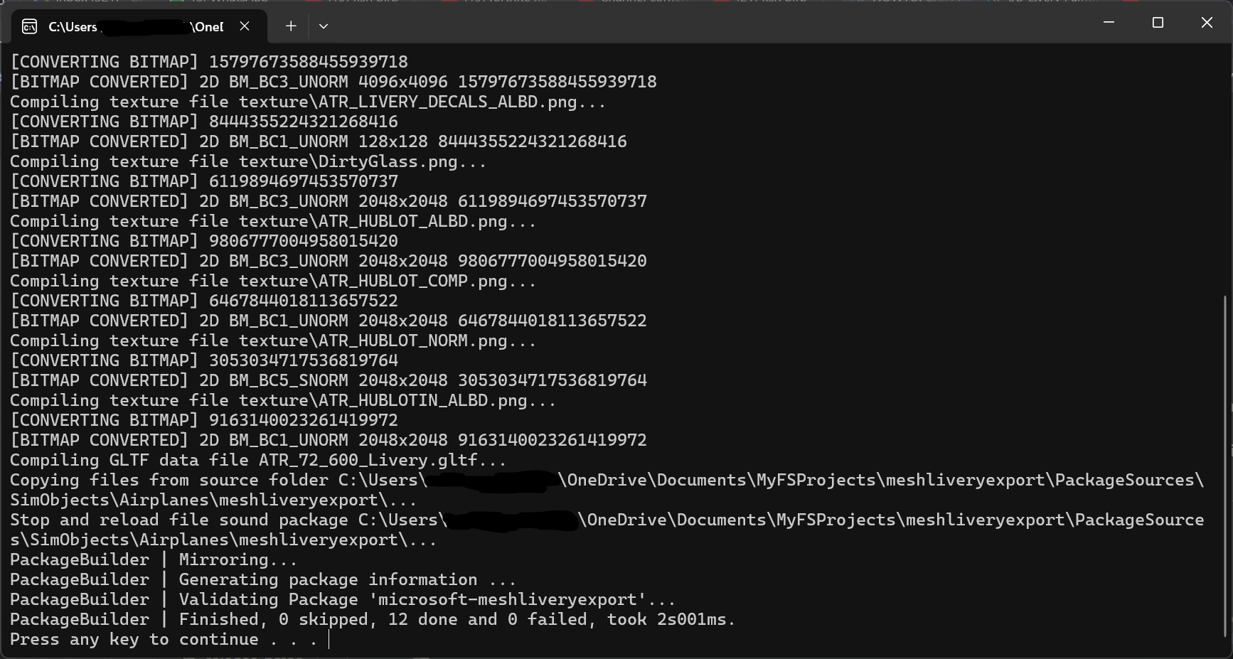
A successful build should look like this, with 0 skipped and 0 failed, just like in the in-game console.
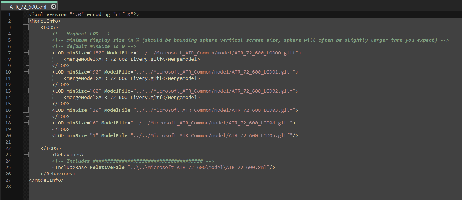
The next process is to finally utilize the submodel merging feature, and merge the models using parameters in the object .xml file in your livery folder.