I practiced on a 1’ aluminum pipe today.
Wow. It doesn’t take much.
I’m not ready to take my current test bed sim apart yet.
I’m going to finish the new panel first then do a disassembly and reassemble
I have been using and tested XPforce with the FFB2 that came yesterday.
Seems pretty straight forward to setup.
I am building this with out the Saitek house and will put it behind the new panel I’m building.
I like having the display working so I might just extend the current harness and mount the original board in the new panel. Even though I fly exclusively in VR I peek at the clock occasionally to make sure I don’t lose track of the outside world. ![]() .
.
Do you have a link by chance?
The ones I bought are not available anymore. Probably because I got them 6 years ago. These ones will do uxcell 5 Pcs 10K OHM Linear Taper Rotary Potentiometer 10KB B10K Pot Zinc Plating with 13mm Shaft: Amazon.com: Industrial & Scientific
I cut the end off to make it shorter. See the STEP drawing for the length.
I took a bunch of pics of the insides. Thought I uploaded them to Imgur but I guess not. I’ll do that tomorrow.
I have another FFB joystick that I will mark the the cut lines on the PS board so you can see where it needs to be cut.
1 Like
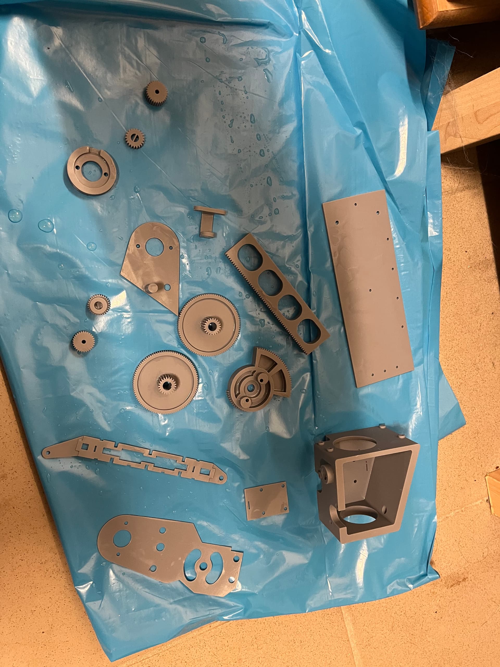
Started the build of this today. My roll dual gear assembly needs some tweaking. It is 1/32 to large. Think the 3D printer left to much excess. I am going to have to have file each tooth so the motor drive gear interfaces better (too tight right now). I’m building this out side of any space constraints of the Saitek case so I’ll mount the boards differently. I’m toying with the idea of wiring the MS FFB2 buttons up on a separate panel or maybe though the Saitek yoke. They are all just buttons so extending the buttons is possible. Do you see a way to make the pitch axis longer? I haven’t assembled it yet but 100mm seems short. Of course that is the length of the pot though.
Properly calibrating your printer is a must. Start with the extruder then the axis. There are some great articles on how to do it. My prints are consistently within .02mm of the drawing.
https://www.amazon.com/uxcell-Variable-Resistors-Potentiometer-Potentiometers/dp/B07W3XCW2D/ref=mp_s_a_1_6?crid=38Y1RN0PNO3TI&keywords=slide+potentiometer+128mm&qid=1646049727&sprefix=10k+slide+potentiometer+128%2Caps%2C1108&sr=8-6
Should have no issue splicing 2 racks together with F360. Cut the linear slide a little longer and you’re go to go.
Some pics. Many if these have original 10-turn pot. I will update them once I take it back apart to put in the cord pass-thru cover.
https://imgur.com/gallery/S2Lms5A
2 Likes
Wish I owned a printer. I had our local library do it for .05/gram. It’s not so far off though. Just have to clean up the teeth.
I’ll make sure everything is good to go then lengthen the pitch with this pot. I have no space constraints so that’s a bonus. This will be for the modular panel I’m building.
Still love how simple this is. ![]()
![]()
Saitek Yoke … checked
Microsoft Sidewinder Force Feedback 2 … checked
Mechnical parts … checked
3D Printed parts … ongoing
so exited ![]()
For me:
Saitek Cessna Yoke … check
Microsoft SW FFB2 … check
Mechanical parts … check
3D printed parts … check
Time … … … none …
Also excited though! ![]()
WOW, those are nice. What printer did you use? Did you print out the metal pieces as well?
Hi,
I’m using a Phrozen Mega 8k SLA Printer. The metall pieces are not so well because there are bendable, too thin. I guess with a little redesign it could be possible to use all parts with plastic.
I’m working in an company with metal laser cutters so i will recreate them on metall.
I won’t destroy the Sidewinder FFB 2 so i will extract the electronic components to a separate housing with connectors for using with the Sidewinder FFB and Saitek Yoke FFB (Plug and Play). For this I’ve bought 775 motors on amazon and printed all gears are needed.
I hope it will work.
1 Like
See this link regarding motor upgrade. MS Sidewinder FF2 hacking
I’m using a 775 12:1 geared motor for my Saitek pedal mod. The amp draw blew out a 3.5a motor controller. That’s more than the MS board can handle. I have a 15a controller that I’m wiring in tonight, along with a 20a current sensor to get a more accurate idea of the actual current draw of the 775 motor.
I’m going to order their mini printer. Those prints are just too pretty to pass up. Let me know how those gears hold up. I’m using annealed PLA and have had no issues at all.
Hi, i’m wondering why a motor controller update is needed. For me the 775 Motors seems to be the same as used or the MS Sidewinder FF2?
My Saitek Yoke electronic was broken 1,5 years ago and I’ve used an Arduino Leonardo with this Library (https://github.com/MHeironimus/ArduinoJoystickLibrary to repair it, works fine.
I’m thinking about to let the MS Sindewinder FF2 and using an Arduino with two BTS7960 motor drivers and the Fino library https://github.com/jmriego/Fino based on the library shown above (drivers are ordered).
First Tests with an RC Servo (for testing) were promissing. I will create a separate housing for the elecronic and connect it to the Yoke by connectors. This will give me the possibility to extend it with the rudder pedals.
1 Like
the 775 motor is about twice the size of the MS motor. Not sure how you intend to combine the MS electronics with the BTS7960’s. Looking forward to seeing this come together though.
Hi,
my new plan is to create a complete Yoke without any party of the Microsoft Sidewinder FFB 2 because i dont want to destroy it. I wanna use wit for flying Airbus or Helicopters.
What i want to do:
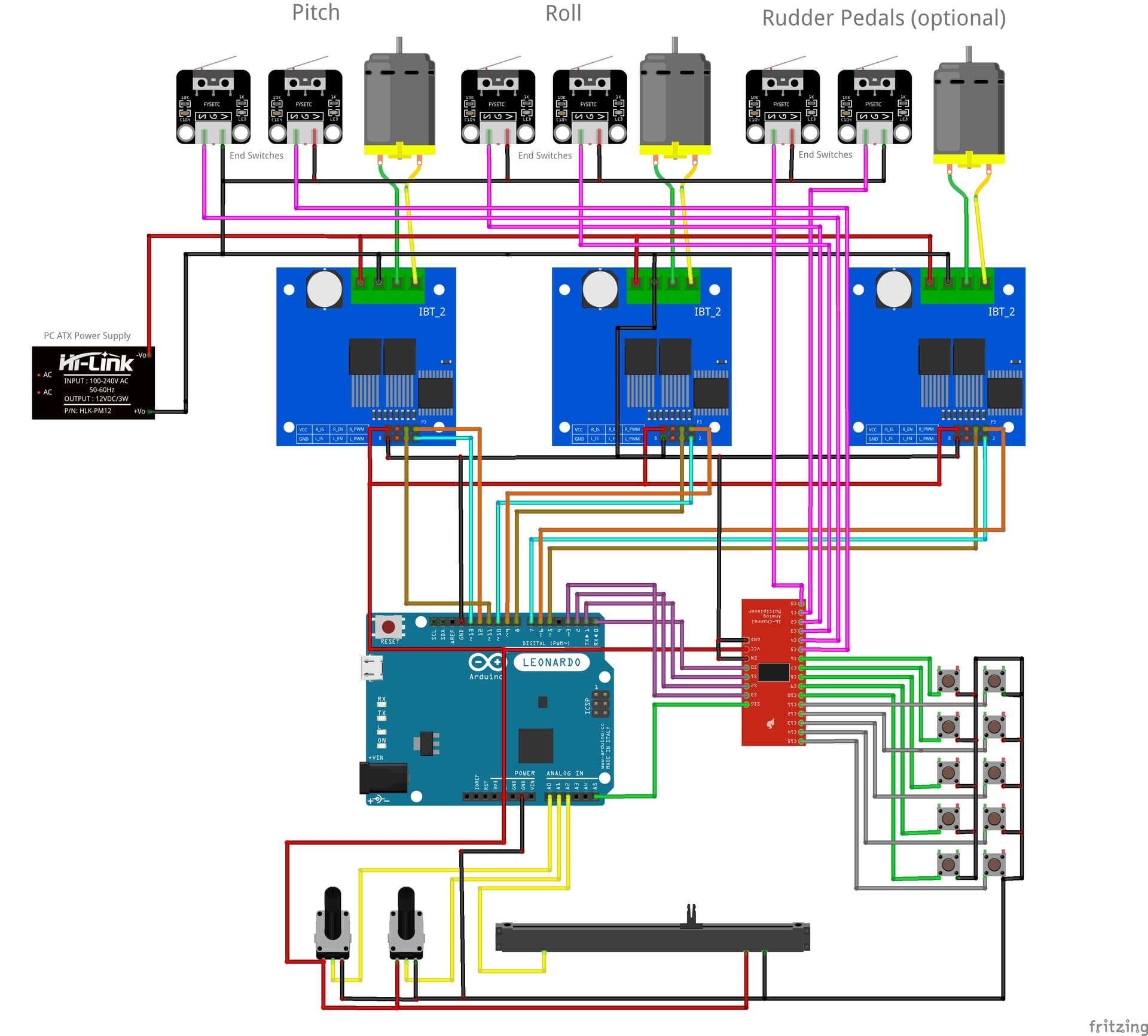
I want to use an Arduino Leonardo with two BTS7960 motor drivers. I want to use your Saitek Mod without any Saitek Yoke. Instead of the Saitek Yoke i want to use a Thingiverse selfmade Yoke https://www.thingiverse.com/thing:4884092 in compbination with your mod. As Ardiono Software i want to use the Fino (Arduino Joystick with force feedback) Library https://github.com/jmriego/Fino. i have party tested it with my Arduino Leonary, the MotoDrivers and the 775 Motors and it seems to work.
In addition to your mechanical parts i want to add some end switches, too, to prevent the motord to go over the end positions.
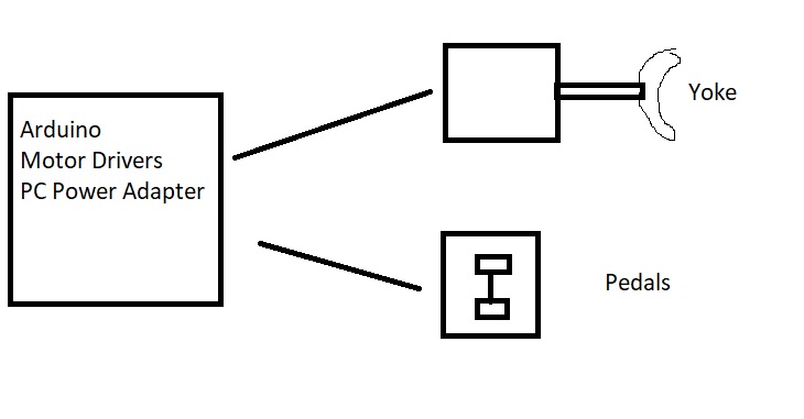
The electronical party (PC Power Supply, Motor Drivers, Arduino) will get an deparat housing where i can insert optionally an third Motor Driver for the Rudder Pedals.
I’m working on the shematic and the Arduino Programm and i will post everything (Images) here or on github (code).
Here is a small Plot of the Electronic (not tested, only the first plot)
1 Like
Ah, I understand now. I currently have a 775 motor connect to my Saitek pedals. While I don’t have end switches I do have a BTS7960 board, 30a meanwell PS, and an Arduino Mega2560 hooked to it. I’m working on a Mobiflight profile to run it becuse I don’t know how to code. I’ve looked at the library you mentioned but just don’t understand it. Whether too old or too much weed in my youth, I just can’t wrap my brain around it.