Looks to me like they are diverging at first, then converging. Your heading is lagging your track. It’s only a degree or two lag, and not very pronounced, as I’d expect in a 172.
The WBSim 172, and Kodiak, have the following values for:
| Plane | Model | Aileron Up Drag Coef | Aileron Down drag coef |
|---|---|---|---|
| wbsim-aircraft-c172sp-classic_1.0.6 | wbsim_C172SP_Classic_Skis | 0.5 | 2.5 ; 1.5 |
| sws-aircraft-kodiak-wheels__20221208 | SWS_Kodiak_gear | 0.2 | 1.89 |
It makes sense to me that the Kodiak demonstrates more adverse yaw than the WBSim 172, based off of these values. They aren’t the only ones affecting it, but they are a contributor, with the first value <0.5, and the second >1.
Don’t understand this. Adverse yaw manifests itself when entering and exiting a turn/bank. So it’s at this time that you need rudder. During the turn, you don’t need rudder (at least ideally).
Using magnetic track and heading to look for the adverse yaw might be difficult because you have other effects like wind playing a role (heading and track differ in the plots even in the straight parts so there is some wind (or skidding/slipping) going on. Furthermore, with such slow turns/shallow banks, it will be difficult to see adverse yaw at all.
You could use the Simvar TURN COORDINATOR BALL. If we assume that the sim is calculating the “amount of coordination” correctly, this value should show you the uncoordinated phases due to adverse yaw when entering or exiting the turn (and you are then independent of wind).
1 Like
Wind was completely turned off in custom weather. Not even 1kt.
It’s not slipping either as there is zero wind. I’m not sure why there is a difference if I’m honest. There shouldn’t be.
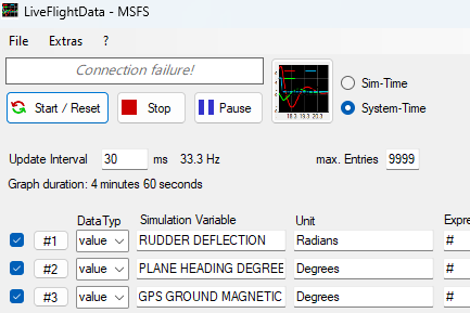
This is what I was using. The default for the bottom two was Radians, I just changed that to Degrees to let LetFlightData do the conversion for me.
Good shout on the turn coordinator. I had considered that, the discarded it as I wanted to ensure I wasn’t measuring some other aspect of the sim that may not be modeled as well as it could be.
But I’ll try that after lunch, for both planes.
Just answered a long-standing question that is in my mind every time I press the YD button Does this actually do anything?
2 Likes
What does this have to do with wind?
I think you mentioned this yourself, or I misunderstood.
I can’t explain why there is a slight difference between my heading, and ground track in those graphs because they should be identical. Its either a quirk of the graphing software itself, or perhaps the unit of measurement. But as far as I could tell there were no external forces to explain the difference, nor what the AP was doing which was holding altitude, and heading.
Annoying the program won’t let me connect to “TURN COORDINATOR BALL”, I just get an error if I try both the MSFS, and SimC versions of the program.
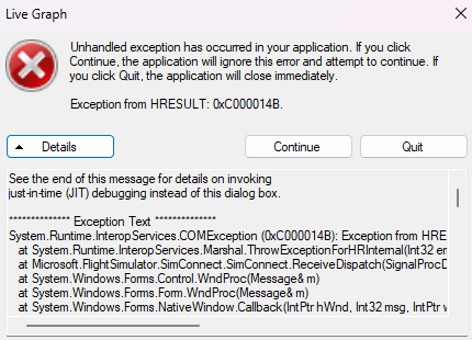
The other values still work though.
SPAD can read it though, and will output to disk. It doesn’t look as good, and the data a bit messy, but essentially when I make a left turn, the turn co-ordinator goes to minus values, and when I make a right turn, the co-ordinator show positive values. When co-ordinated its close to 0.
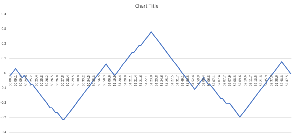
These were roughly 90 degree turns, starting with a left turn, and the corresponding drop into minus figures at the start of the graph. This was for the Kodiak, by the way.
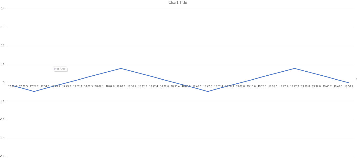
Now for the WBSim 172, adjusted to the same -0.4 to 0.4 scale:
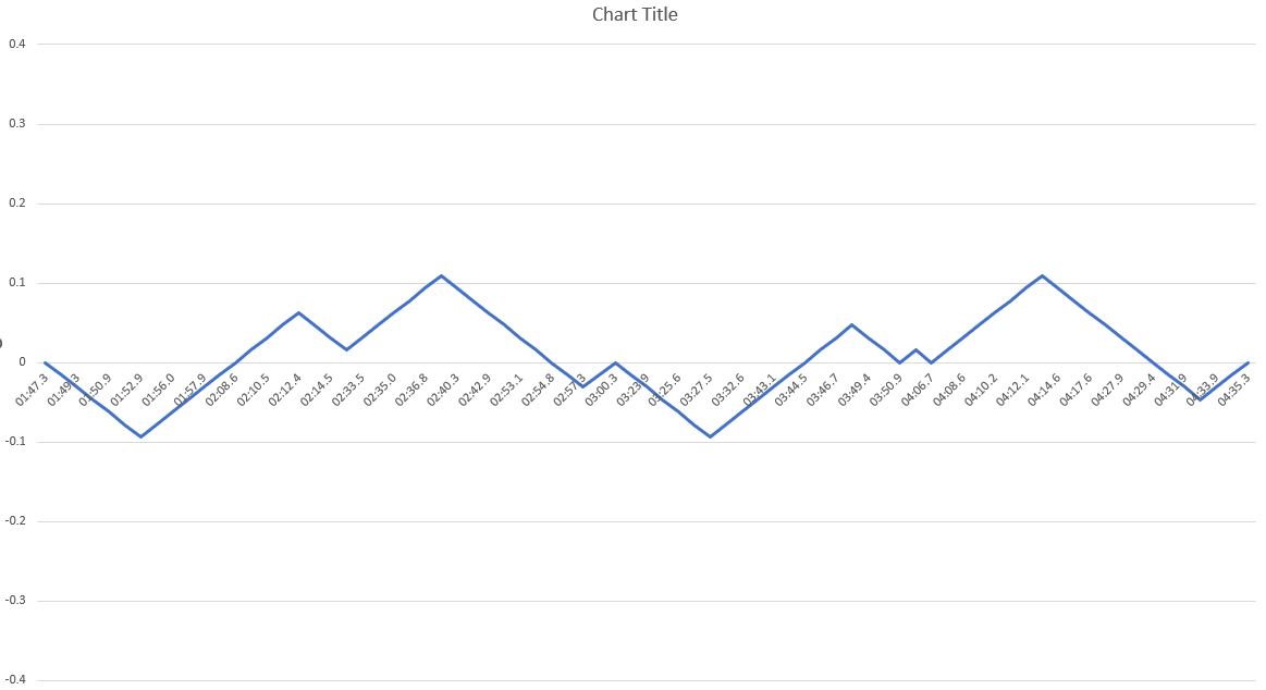
So you can see that both planes do have adverse yaw, the Kodiak just demonstrates a greater amount.
Incidentally, the little steps you see, such as at 02:14.5, during a right turn, and 02:57.3 during a left turn, is where the AP has corrected to avoid overshooting the selected heading.
For good measure, here is the Asobo stock G1000 172:
You can see the WBSim folks did some work on the AP because there was “no jumpiness” here, and even less adverse yaw.
I think the bottom line is that unless a pilot with experience in a given type of plane says that it has realistic adverse yaw, its a difficult one to judge. Determining whether something was simply on or off was so much simpler! ![]()
1 Like
I removed the ‘‘realistic’’ from adverse yaw and updated the description, otherwise it would lead to misunderstandings.
Some aircraft are designed to only have minimal adverse yaw, so they are realistically modelled if they don’t need much rudder input at all (I simply didn’t know this).
But it’s fun to use the rudder pedals in flight, instead of just on or near the ground.
So the new idea is to only list aircraft which does need some fair amount of rudder input for a coordinated turn / to counteract adverse yaw, as this can be very interesting for people with rudder pedals.
(If it’s realistic or not is another question, which this list doesn’t aim to answer)
2 Likes
Got a new one for you:
| Plane | Model | NPS | CFD | SBS | |||
|---|---|---|---|---|---|---|---|
| orbx-aircraft-pac750 | orbx-aircraft-pac750-agriculture | 1 | 1 | ||||
| orbx-aircraft-pac750 | orbx-aircraft-pac750-cargo | 1 | 1 | ||||
| orbx-aircraft-pac750 | orbx-aircraft-pac750-pax | 1 | 1 | ||||
| orbx-aircraft-pac750 | orbx-aircraft-pac750-skydive | 1 | 1 |
1 Like
Yes, but you don’t slip because of wind. The wind drift makes heading and ground track differ but you are still coordinated, the relative is coming from head on. In a slip, it is somewhat the other way around: you let you nose (intentionally or not) head in a different direction than the relative wind.
The graphs look weird to me. I would expect the turn coordinator to be at zero during the turn and show peaks when entering and exiting the turn (without rudder).
2 Likes
Yes, its weird. Also the thing to realise about how Spad works is it only records a data point when something changes. So if I sat controls centred for half an hour, and it really did show 0 with no changes, your graph would be a dot!
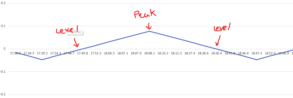
As I enter that right turn, you can see the number go positive, hit a maximum, then eventually return to 0. It might be clearer seeing the actual numbers that I generated the graph from.
If it were the other tool you would see the graph continuously logging even if the data doesn’t change. But for some reason it just won’t allow me to read from the SimVar for the turn co-ordinator.
I just figured out why I couldn’t read the turn coordinator in the other tool. I had to change the unit of measurement to “Bool” from the default.
![]()
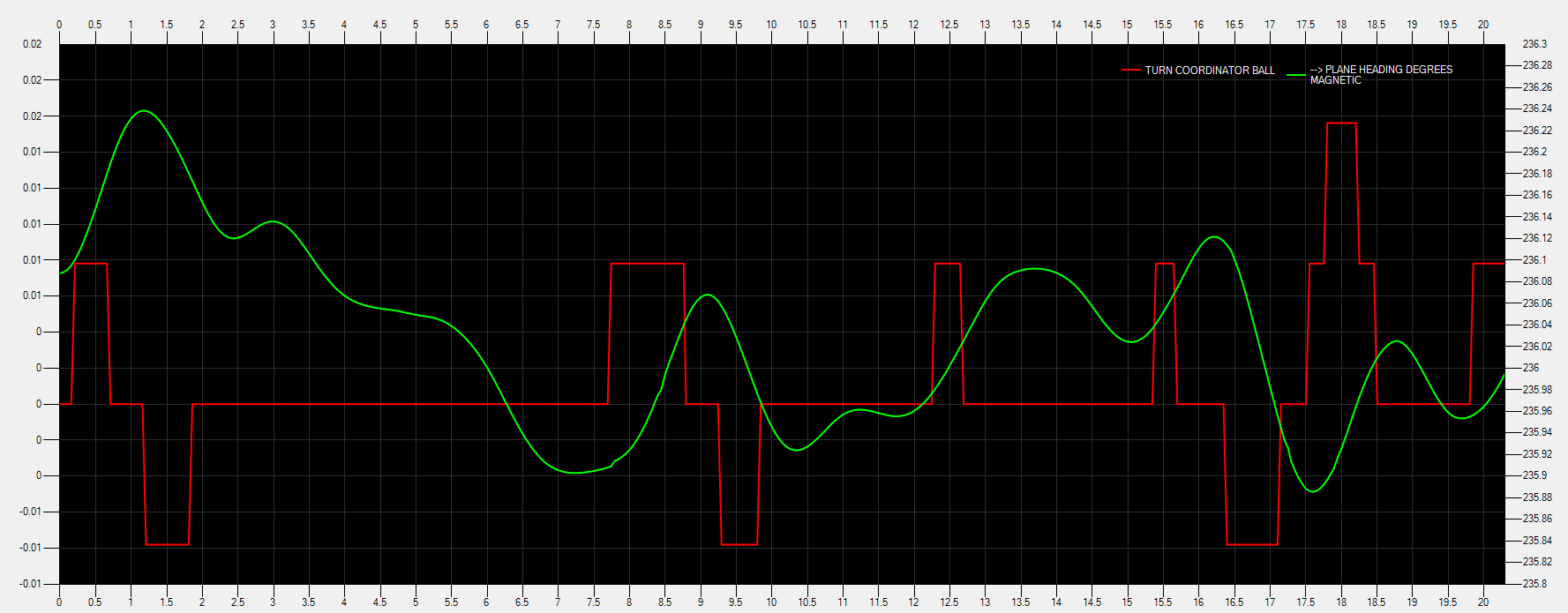
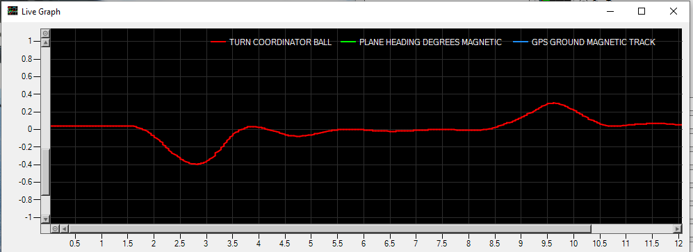
Just playing around with the PAC 750 XSTOL, so zero wind in level flight it bounces around close to 0. The scale of the graph makes it look more harsh than it really is, but I can draw the two graphs with separate scales to make the graph easier to interpret.
For example, here’s 10 seconds of level flight at 50ms interval. It looks really jerky till you look at the scales. The changes are miniscule.
Here’s nearly three minutes:
A bool is a 0 or 1 (no or yes) value; something weird sounds like it’s going on there if you’re graphing that. ![]()
2 Likes
True, but it seems to be graphing it okay all the same. ![]() Those values are exactly what I see in Spad.
Those values are exactly what I see in Spad.
What the program was complaining about was the default unit of measurement for that Simvar, which is “Position 128 (-127 to 127)”. That’s why the program was crashing.
Let me try it again quickly with “Number” as the Unit instead, and in the G1000 172 as well as I already have graphs for that.
1 Like
Yeah, the graph results on the turn look reasonably sensible at least. ![]()
Coordinator jumps around a bit during the aileron usage, partly stabilizes during the boring part of the turn, then does the other way on the other end. So the ideal is to see that difference when not using rudder, and have it be minimized when using a “realistic fo rthis plane” amount of rudder.
Nice! Good work.
1 Like
Here’s the 172 G1000 I did earlier, but with the better tool.
The other thing these graphs make me think is that some devs. might need to work on their autopilot feedback loop. This one is very smooth. There is very minimal overshoot, no aggressive bank then backing off before turning again as the PAC 750 XSTOL shows.
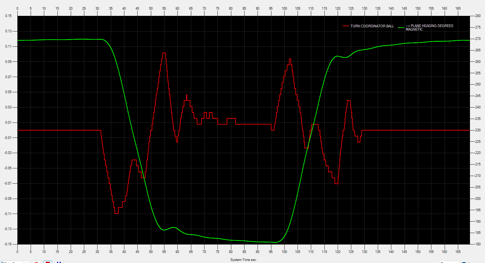
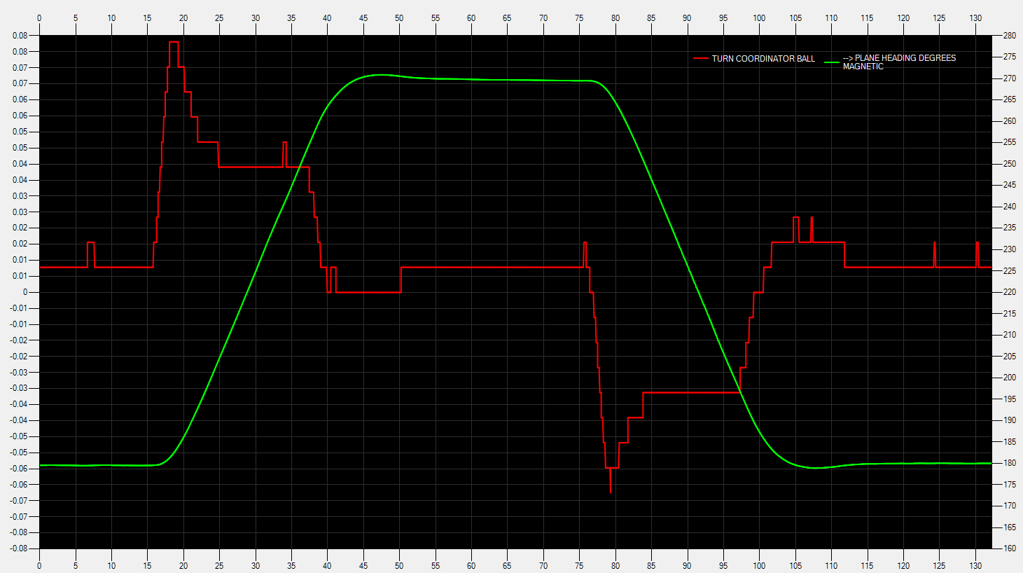
I did a test with the C172 G1000 without autopilot and without rudder input:
Here is the Turn coordinator ball position (+/-1 is maximum):
Here is heading and track (in radians):

2 Likes
Black Square Analog Bonanza added for CFD
Black Square Analog Kingair added for CFD NPS
3 Likes
Another Update to the list:
- Adverse yaw removed - too hard and unclear which aircraft to list, keeping the list more clean
- Added subcategories 3rd Party and MSFS stock/ premium content
3 Likes
Please don‘t remove adverse yaw from the list. It is an area where the sim is lacking in realism, and it would be great if we could distinguish between the developers who put more effort into the flight modeling, and those who don‘t.
It seems particularly adverse yaw is a good differentiator between the „toy game“ plane makers and the more serious ones for us users.
What exactly is different in the new adverse yaw modeling, compared to the old way, where the SDK stated it would be an „automatic“ result of airframe geometry?
Since there are several side force effects in this sim, that make many people scratch their heads, why it feels so unrealistic (ground handling in cross winds for instance) it might very well be, that the effect of adverse yaw is falsely diminished in the air, and therefor harder to demonstrate/measure.
Like if for some reason, the vectored side airstream force hitting the vertical stabilizer is exaggerated in the sim due to some error in the underlying math, it would neutralize adverse yaw effects to a certain degree.
There are airplanes in the sim - e.g. the Pilatus PC-6, available as both stock aircraft and 3rd party enhanced version - which should demonstrate strong adverse yaw effects. Due to their geometry (big leverage from long wings) and also reported by IRL pilots (for IRL planes).
Have you experimented with speed in your measurements? Because depending on which constructive method plane makers used to decrease adverse yaw effects, these never work proportionally over the whole speed envelope, exposing stronger adverse yaw effects only in certain ranges of the speed range of an airplane.
And not sure the turn coordinator is an effective instrument to measure adverse yaw, lacking the knowledge how directly or not it shows side forces, or if it has its own math for that,
1 Like
I totally agree with you, as far as I understand the ‘‘new adverse yaw’’ is still some kind of workaround trick from Asobo. That’s why aircraft which don’t come up with own custom codes like from GotGravel don’t feel that realistic or don’t have any adverse yaw at all.
I’m gonna continue the Aircraft list for Adverse Yaw right here
(now linked in the OP together with the Ground handling list):
Realistic Adverse Yaw / Aircraft list
And there is also a wishlist thread for Adverse Yaw improvements:
Adverse Yaw - missing in almost every Airplane
5 Likes