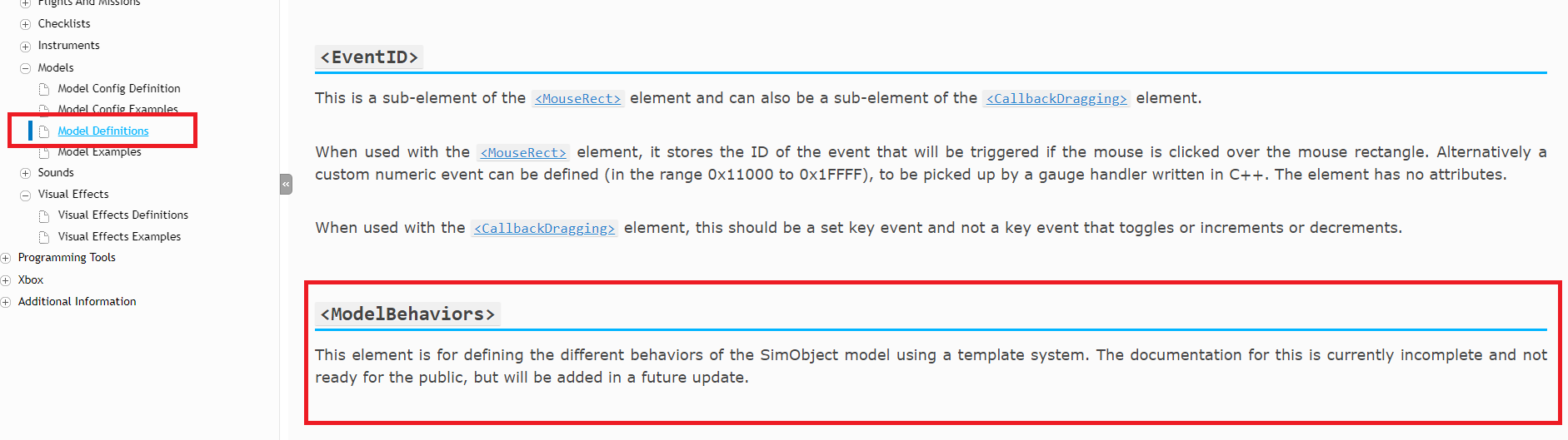
Okay so, for adding the effect to a SimObject… You will need to use the FX.xml model behaviour template, so to start with you need to make sure that you add the following line into the <ModelBehaviors> element:
<Include ModelBehaviorFile="Asobo\Generic\FX.xml"/>
Once you’ve done that, you can start to use the Component Templates. For this, first add a Component with a unique string ID attribute like this
<Component ID="#MyFXSpawner#">
</Component>
This component can define several <DefaultTemplateParameters> that will be applied to all Visual Effect component children of your named component :
<Component ID="#MyFXSpawner#">
   <DefaultTemplateParameters>
   </DefaultTemplateParameters>
</Component>
The available default parameter elements are :
-
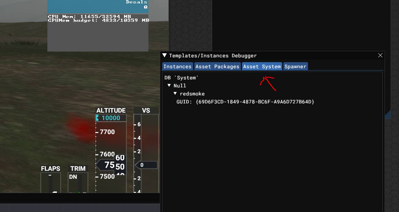
FX_GUID: The GUID of the VFX Template. This can be found as the “InstanceID” attribute value of the <VisualEffect.VisualEffect> element in theVisual Effect XML asset source file
-
<FX_CONTACT_POINT_ID>: The index of the ContactPoint to use in case the node you want to attach a Visual Effect to is not found. If you want to use a ContactPoint instead of a Node, use Node names such as __USING_CONTACT_POINT__ (for example) to be sure that you won’t target any node you are not aware of in the Component “Node” attribute value (explained further down this page). Use -1 if you don’t want any. The contact point index references the contact points defined in the aircraft CFG files.
-
<FX_OFFSET_X>: X offset in the coordinate space defined for the Visual Effect, applied to the Visual Effect after spawn (meters)
-
<FX_OFFSET_Y>: Y offset in the coordinate space defined for the Visual Effect, applied to the Visual Effect after spawn (meters)
-
<FX_OFFSET_Z>: Z offset in the coordinate space defined for the Visual Effect, applied to the Visual Effect after spawn (meters)
-
<FX_ROTATION_OFFSET_P>: Pitch rotation angle in local space (degrees)
-
<FX_ROTATION_OFFSET_B>: Bank rotation angle in local space (degrees)
-
<FX_ROTATION_OFFSET_H>: Heading rotation angle in local space (degrees)
With that done, you can then define you spawning rules as further components like this:
<Component ID="#MyFirstUniqueSpawningRuleID#" Node="#MyNodeName#">
    <UseTemplate Name="ASOBO_GT_FX">
    </UseTemplate>
</Component>
Now, the <UseTemplate> element is not enough to generate the Visual Effect and you will have to set at least one <FX_CODE> element with an RPN code expression inside. This expression is evaluated by the simulator and when it becomes true the Visual Effect is spawned. For example:
<UseTemplate Name="ASOBO_GT_FX">
    <FX_CODE>1 0 gt;</FX_CODE>
</UseTemplate>
As mentioned previously, the “Node” attribute value has to match a node in your mesh model, unless you don’t want to use a mesh node and purposely put a ContactPoint index. However, you might want to use the ContactPoint as fallback eventually when some LODs don’t need it. For that, here are the additional parameters available to the <UseTemplate Name="ASOBO_GT_FX"> element that can override the default parameters defined earlier:
<FX_CODE>: RPN code that should return true in order to spawn the effect<SURFACE_TYPE_N>: contains a string corresponding to the surface type that will spawn the following effect<FX_SURFACE_TYPE_GUID_N>: the effect template GUID
If you defined these tuples, they will be prioritized over <FX_GUID> which will become a default choice. Note that the value N for the elements listed above is from 0 to whatever you need, but they should always be concurrent, e.g: 0,1,2,3 and not 0,3,1,2. Below is a further example using these elements:
<UseTemplate Name="ASOBO_GT_FX">
    <FX_CODE>1 0 gt;</FX_CODE>
    <SURFACE_TYPE_0>CONCRETE</SURFACE_TYPE_0>
    <FX_SURFACE_TYPE_GUID_0>{B115D24C-2385-4DEC-85A0-040CED485481}</FX_SURFACE_TYPE_GUID_0>
</UseTemplate>
This information will be in the next update to the SDK, and I’ll see if we can’t get the online docs updated sooner with it.