For some reason Asobo treats turboprop engines different than jet engines.
At ~50% throttle all three turboprops are already close to overtemp when sitting static on the runway, which shouldn’t be the case.
As reported already many month ago, Asobo apparently doesn’t consider the velocity of the air which is being sucked into the engine on the turboprops at 0kts.
This results in a completely unrealistic ITT behavior with increasing speed.
TBM @59% throttle = 50% torque. (~identical values for the 350i at 40% throttle = 51% torque)
000kts, ITT 800°C
010kts, ITT 700°C
150kts, ITT 600°C
C208 @59% throttle = 1500ft/lbs
00kts, ITT 700°C
15kts, ITT 600°C
80kts, ITT 500°C
Longitude: 0-150kts = -15°C ITT, which is much more in line with RW values.
A turboprop engines ITT should react like in a normal jet engine, since the only signifcant difference is the size and speed of the fan at the front end.
1.It is possible to remain static at 0kts with close to or at max thrust/power on a jet/turboprop IRL
(SL & ISA) without exceeding ITT.
This is only possible with jets in MSFS.
MSFS turboprops are overtemping already at ~50% power, which doesn’t make any sense
2.Acceleration from 0 to 150kts in MSFS jets (and IRL) results in no significant (15°C) ITT change.
With the MSFS turboprops ITT drops whopping 200°C, but it shouldn’t (significantly) change.
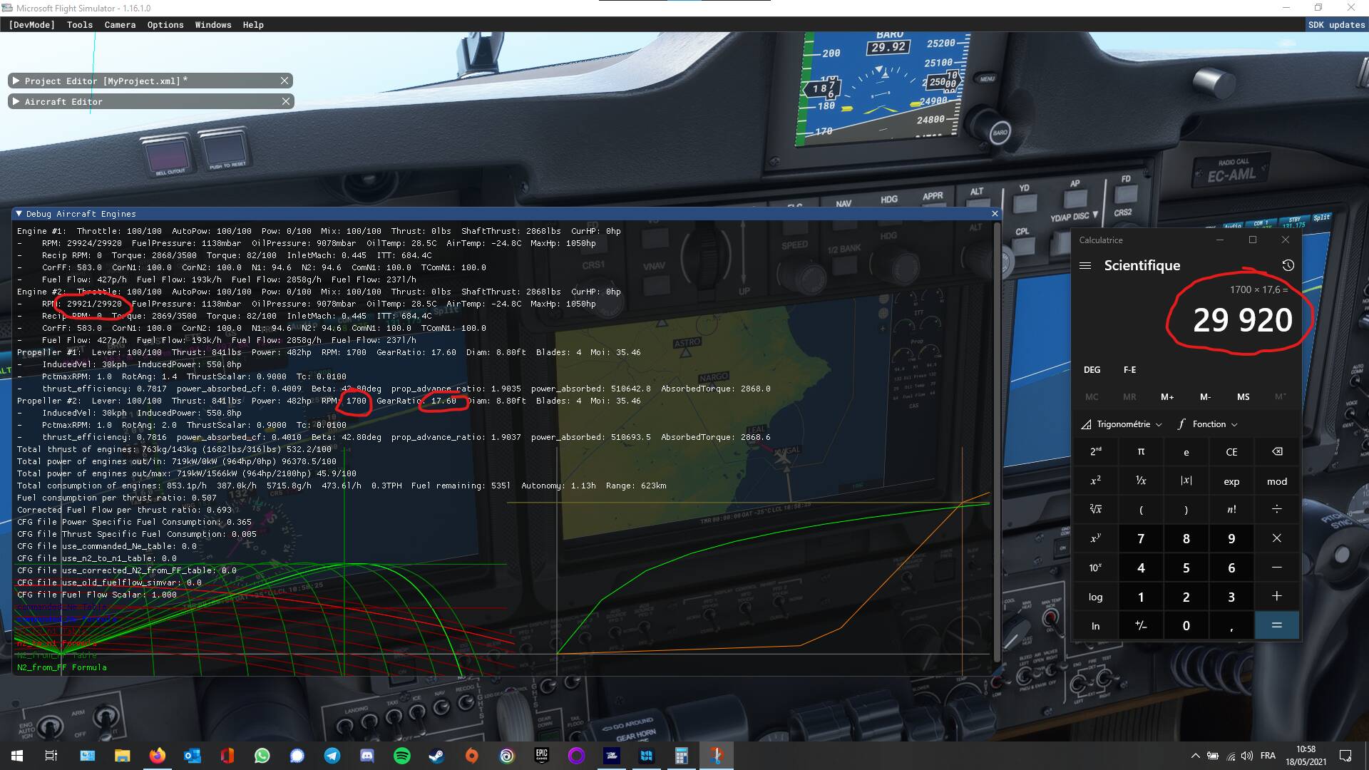
The PT6A-66D is flat rated at SL up to 73C (!) according the EASA TC, so the TBM should not reach anywhere near peak ITT static on ground. And yes Ram Rise isn’t that significant at least on the turboprops I have flown, definitely not in the hundreds of degrees (have flown PT-6, TPE-331 and PW100).
Another point is that idle doesn’t necessarily means the lowest temp on a jet engine.
Can’t remember the PT6, but e.g. the CFM 56 runs noticeable hotter at idle than at low thrust settings, static on ground and in flight.
I haven’t flown PT-6 in 10 years so not sure. I will check on the ATR tonight, I’m pretty sure its the same. ITT is pretty high on ground when idling props feathered, then drops when unfeathering (which also spools up the engine on ATR to keep prop speed above min generator speed). The TPE was always running against EGT limit in flight but that is a direct driven turboprop instead of free-turbine and flat rated up to 20C OAT or so, almost always EGT limited.
There isn’t even a take-off torque table in the TBM930 POH, at least I can’t find it. I guess the point at which ITT becomes limiting is outside the environmental envelope anyway. The take-off distance tables are all valid for 100% torque, bleeds - auto.
Anyway, I guess we can all agree it must be possible to achieve max torque while static on ground at SL in ISA without exceeding max. ITT.
Edit: There is a note: Between ISA +30 and ISA +37 it may be necessary to cut-off the “BLEED” in order to set TRQ = 100% during take-off while respecting engine limitations.
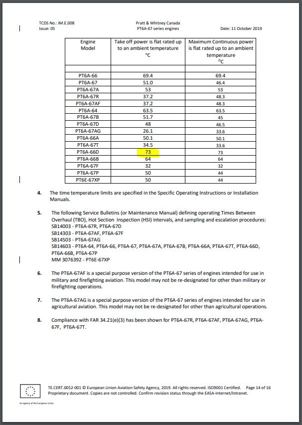
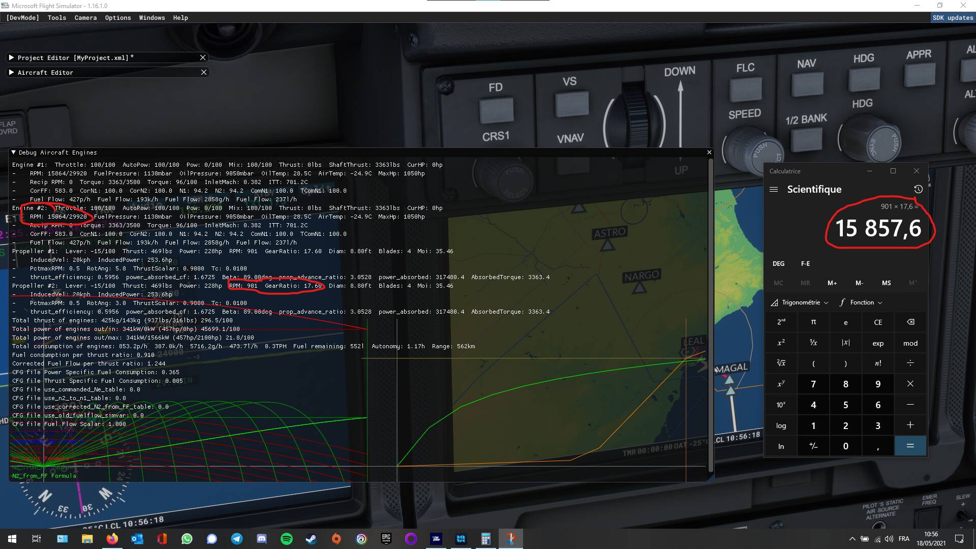
Just out of curiosity does Asobo simulate the free turbine principle properly? What is the ratio between prop RPM and engine RPM in MSFS? Does the prop RPM drop off quicker than the engine RPM or does the ratio remain the same over the whole operating range?
But the ratio while stabilized does change right? Engine RPM / prop RPM is a different ratio when feathered compared to unfeathered and full power? In other words the power section and compressor section are not physically connected?
Well, looking at the TCDS for both the plane and the engine, the config files are off for some values.
For example, the feathered beta angle is +80° +/- 0.5°, and is set to 89° in the engines config file.
The gas generator (the free turbine) should have a rated RPM of 39,000 RPM 29,894 RPM (EDIT : 39,000 is the max permissible RPM), and it is set to a default of 29,920 in the config file.
By the way this 29,920 RPM looks like a default value for MSFS because you can find it in the 747 engines config as well, for example. I have not checked but I guess we can find it in all the jets.
I think I understand the problem of the free turbine and its solution in the context of MSFS.
It looks to me that MSFS is considering a turboprop like a turbojet with a prop attached to the end.
I’m thinking it could be possible to get a “fake” free turbine by considering the N1 as N2 and N2 as the free turbine. Then it would be possible to use the engine tables to tweak the relationship between N2 and the free turbine, set the gear ratio to 1 thus having prop RPM depending on N2.
Hmm, why would N2 be the free turbine? I would think the low spool would be the power turbine and the high spool the compressor turbine.
The problem is I guess that MSFS doesn’t see the power turbine completely separate? On a turbofan the low pressure compressor and the fan together form the low spool. Is it possible to create a triple spool turbofan in MSFS? Then the low spool could be the gearbox output axis while the intermediate spool is the power turbine (gearbox input) and high spool forms the compressor spool. In the real PT6 there are only 2 spools of which the power spool is connected to the reduction gearbox so maybe this can be simulated somehow with three spools?
Just thinking out load, I have no idea how all of this MSFS stuff works. I would think MSFS considers N1 and N2 as being part of the compressor system while N3 is never part of a compressor system (in real life) and only drives the fan on a triple spool turbofan. Maybe a gear ratio of 1:1 between N1 and N2 so they are basically one single spool? And then N3 forms the propeller.