DIY 6DOF Motion Simulator VR Cockpit project + pendular yoke, throttle quadrant, switch boxes and MCP/Autopilot

After enjoying my ultra-low-budget 2DOF Motion Simulator for 3 years I decided to build a budget 6DOF Motion Simulator. The jump from a static VR cockpit to a moving motion rig was as much of an immersion leap as from flatscreen to VR, if not more. Upgrading from 2DOF to 6DOF will be awesome!

EDIT: Here’s the progress so far

The hexapod geometry with 6 motors allows for 6 degrees of freedom with rotation and translation in any direction.

I’m also reworking the encoder/button/switch boxes. If it works out, it will be the next level of immersion, at least for me. The build will be an ultra-low budget, just like my 2DOF. The cheapest available off-the-shelf 6DOF motion platform costs around $8000 with shipping and some necessary options, and that is too much. I intend to build one for the cost of around $1000 in parts. Let’s hope I’m successful. I’m very happy with how the wooden frame held on, so I will build the 6DOF frame from wood as well. The top platform will be cut from a thick plywood I have lying around.

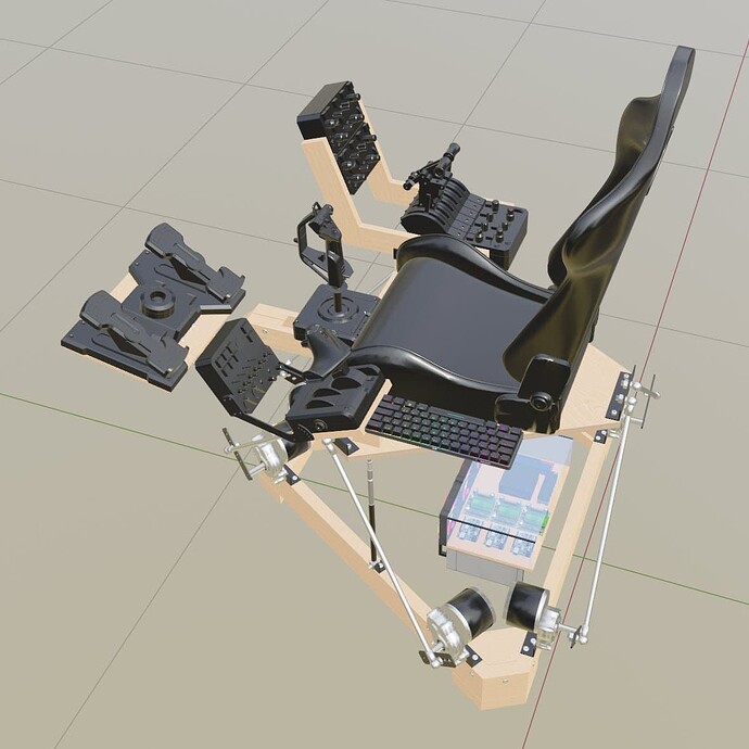
This is the project sketch in the FlightSim yoke configuration. I’ll be using my DIY pendular yoke. The frame will be painted black, but I’m showing a natural wood colour for illustration purposes, so the wooden parts can be easily seen.

FlightSim Joystick/HOTAS Configuration

Racing/trucking configuration.


Note that this is a second priority for me, so it’s not designed to be a low-sitting-position F1 racing rig with a limited range but fast movement. As I’m a Flight Simulation fan, I’m aiming for a smooth and precise motion with a reasonably large range to the limit of what a compact design with inexpensive motors can pull off. Racing can be fan, as is Euro Truck Simulator (and ATS), but those are not as important, so as long as the speed of motion is reasonable, I’ll be OK.

I’m using 6 x 250W Motors, a total of 1500W power supply, 4 Arduino boards, 6 Motor drivers etc.

The Sky is Calling!

3 Likes

OK, here’s my progress so far:

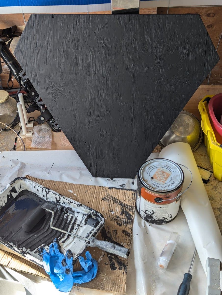
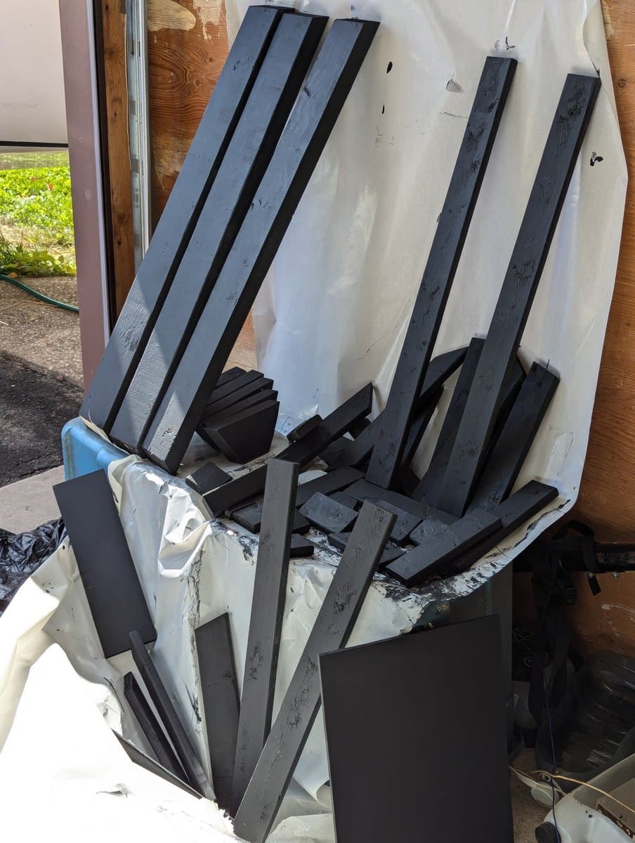
Cutting and painting the frame lumber and the top platform plywood:


Assembling the frame:

Cutting and drilling metal corners:


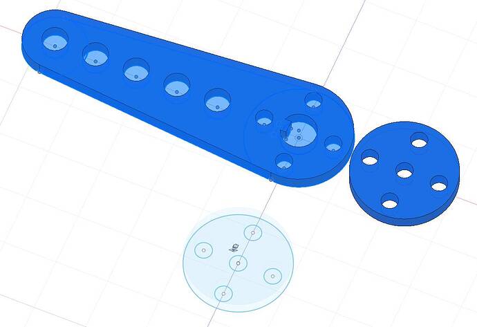
Designing the motor arms - to be fabricated on the waterjet cutter:

More progress:

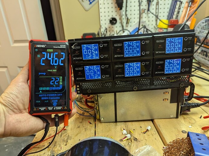
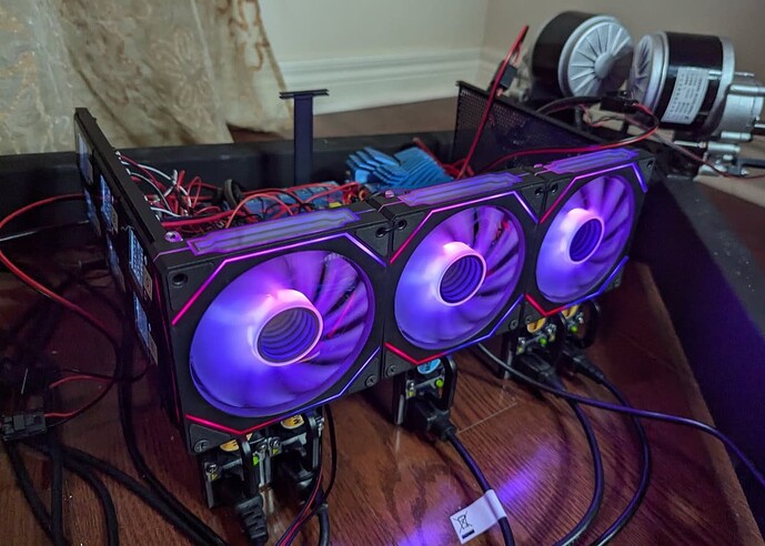
Making the ECB (Electronics Control Box), powering it with modded 12V server power supplies to provide 2 x 24V 750W stacked power supplier, plus a single 12V PSU for all the 12V needs:

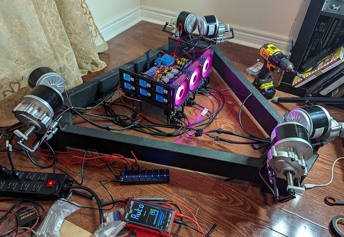
Testing the circuitry:

I got motion!

ECB with working cooling:

Some motors are struggling to keep in place - that’s what the noise is coming from:

The inner mess:

More progress.
Power / Emergency Stop / Button box:

Testing the geometry and the top platform.

I’m moving the motors closer together for optimal geometry.
Next step: fabricating the motor arms and putting the whole rig together. Then come the controls.

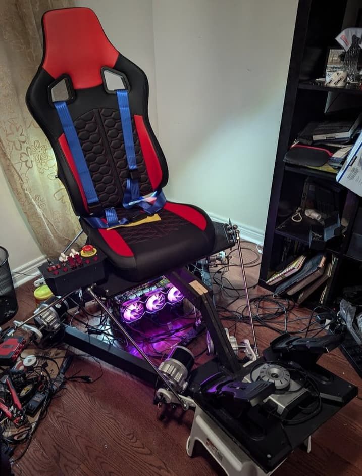
Seat, spine and pedal shelf assembly:

1 Like

Some (careful) testing of the seat, spine and pedal assembly on plastic motor arms. Eventually one of the arms snapped at some later point, but I got the data I needed so I could proceed with other work until I could fabricate the metal motor arms, which was pushed to next week unfortunately. The pedal shelf can hit the front motor arms in some positions, so I will flip the top platform brackets to get a few more cm of height. I also now have measured my maximum top position, so I can install the gas strut, or both struts. I think I’ll start with one, placed at the center, then see if I want both.

2 Likes

This really reminds me of the effort that went into the Floppotron 3.0.

Really impressive work.
I guess the hexapod configuration with the screws rather than with the direct link to the seat would be more expensive?
I wonder, how do you link the controller with the simulator to generate the movements?

Thanks.

If you mean linear actuators, then yes, they are very expensive, even DIY ones. Rotating arms are much more cost-effective. Even the $8000 6DOF off-the-shelf platform uses rotating arms, and all others are much more expensive.

The ECB has 3 Arduino boards using an SMC3 firmware that I modified somewhat, each controlling a pair of motors. On the PC side I run FlyPT Mover software that sends motion commands to the Arduinos. There are other alternatives like SimTools. FlyPT can use many simulators and racing games to get the data from. As long as the game has physics and supports telemetry, it can be used to get the data and calculate appropriate motion. Sometimes when there’s no telemetry, like in Elite Dangerous, direct memory addresses where the physics data is stored can be “hacked” to get the data. I used my 2DOF Motion Simulator with MSFS, DCS, Elite Dangerous, Dirt Rally 2.0, American Truch Simulator, Euro Truck Simulator, BMG Drive, Project Cars, Epic Roller Coasters. 6DOF can be used with all of those and more. I’m only interested in the sims that support VR.

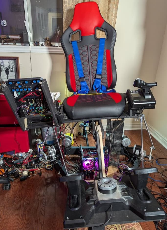
Top platform assembled and attached:

Building left and right panel racks. The left side has the HOTAS and will have a 3D-printed buttonbox, and the right side has the On/Off + Emergency Stop + button box combo, and my 3D printed custom Throttle Quadrant from the 2DOF rig, along with 2 other modules.

Assembling Gear Button Box and MCP/GPS box (work in progress)


3 Likes

Yes, sorry, linear actuators. I just couldn’t figure out the name :laughing:
Hmmm… interesting. I would have thought that you could save on motor power by using a linear actuator, since the movement is “one way” by design, in the sense that you can’t rotate back the screw just by applying weight. Here I guess you need to maintain a torque sufficient to hold all the weight on the platform in position, or am I wrong? Have you figured out the power you need on each motor to move a person with all the hardware on the platform?

Yes, VR is also my case. And I love Elite Dangerous too :sweat_smile:
Wow, this is really interesting. What has always been stopping me is the software aspect, also with my force feedback yoke project I went for a USB HID interface because in that way I wouldn’t had to do anything on PC side, just coding the microcontroller with the USB descriptor and creating my own peripheral.
I’d love to build a hexapod platform, now that I have the space to do it.

Exactly. And not just hold, but mover around with fast acceleration without burning up the motor drivers and PSUs.

It’s a bit of a guesswork, but in theory there should be enough power. 6 x 250W motors should be moving around the rig and me fairly well. I know of two similar projects that are using the same motors and seem to be working OK. But I won’t know for sure until I test it with myself on it, which will happen after I fabricate metal motor arms, hopefully within a few days.
I have installed a gas strut in the center that can support 54kg so it partially offsets the weight of the rig and the pilot, and should also smooth out the movements. I have another strut if I decided to use two, but I’ll try it with one first.

there is a danger of back current when the motors are braking or reversing. I have the rectifier diode bridges to protect the power supplies but we’ll see how the motor drivers hold on.

I have built some HID interfaces based on Arduino Leonardo - the pendular yoke, button boxes, dual encoder box, gear shifter/parking brake etc. I’m and building more. Most use standard Windows joystick HID interface, but the dual encoder box and the new MCP/GPS version are using Arduino Mega + MobiFlight software which can be used to build very powerful MSFS controls.

I’m sharing my progress as I go on, and will publish basic info. If the project is successful, I’m considering writing up all the documentation, full schematics, BOM (Bill of Materials), all the firmware mods, 3D-printed part designs, 3D files with exact dimensions etc. and possibly offering it as a packaged design and the building plans on my website. I’m not sure there is demand, but it does make sense. While basic geometry, software and generic designs exist, everyone who attempts to build a motion simulator has to become a bit of a mechanical engineer and electronic engineer, solve many problems from scratch, make some educated (or uneducated) guesses, order untested parts and combinations of parts from China etc. Costly mistakes are not just likely, they are almost inevitable. Then one has to reorder parts, losing money and weeks if not months. Buying a plan for a hundred or two that will give one a precise parts list, a tested design that works, a working geometry solution with all dimentions, preconfigured firmware, software presets, detailed wiring diagrams etc. would be much cheaper in the end for most people. But we’ll see.

In any case, I hope this project will inspire others to build similar rigs. The immersion leap is comparable in scale to the leap from a flat screen to VR. The more people can experience this - the better.

1 Like

Just out of curiosity, what’s the cost of those motors, with reductors and encoders I guess? One of my biggest issues when I build my yoke was finding decent motors without spending a fortune. Used, I couldn’t find two that were the same. New, it would have been cheaper to buy a commercial yoke…

I’m just looking at DIY linear actuators and -again- the biggest cost seems to be the motor…

So you basically have something like this

under the platfom? With some kind of ball joint to allow the movement on the side? That is a great idea, indeed that should reduce a lot the load on the motors.

The motors are Chinese wheelchair motors - 24V 250W 75RPM. They come with reductors. The cost is only around $85 per motor on average - I got them for only about $65 USD ($89.59CAD) each on Amazon. The encoders (angle sensors) are my own design, made from hall sensors (literally less than $3 for a 10-pack), small magnets and 3D-printed parts. They are frictionless so they don’t wear out and are very precise. Usually, people use hall sensor potentiometers (at around $25 or more each), but they have a moving shaft, which has to be precisely matched to the motor shaft either by a flex adapter or via gears and belts. My design has magnets fixed on the motor shaft, and the sensor on the outside bracket, so the whole thing becomes the hall sensor pot.

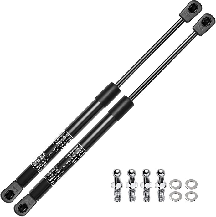
Even better - those are gas struts similar to the ones used on the car hood or trunk:

They are rated at 120lb each (54kg) and come with ball joints. I placed one at the center of the platform for now, will test and see how it works. The motors should be powerful enough to support the weight even without the strut, but it should be better with the strut taking half of the weight, and it should smooth out the movement a bit. I can use 2 struts if I want to, that will almost fully compensate for the weight, but it may be a bit too much for the empty rig, so not sure yet. Depends on the test results.

1 Like

Right, I thought indeed you are in US. Unfortunately on this side of the ocean (Europe) getting that type of material second hand is really hard, or if you go for items shipped from China you have to wait a long time, pay a lot in customs and hope you don’t get a brick.
Procuring the material is the big issue here, depending on the country even new parts are difficult to find.

I bought everything new, not second-hand. The motors could be ordered from China but Amazon was cheaper because of the shipping costs. Actually, I just checked out of curiosity, and if you google German Amazon for “Rafornty 250W 24V 75Min” you get the same motor for 62 Euros. Those are Yalu brand motors. I haven’t confirmed them to be a good choice yet, though I’m reasonable optimistic. So don’t buy them yet :slight_smile:
All the small electronic stuff is ordered from Ali Express, which takes a few weeks but usually is fine, and if there’s a problem they refund the money. That’s how you build stuff cheap :slight_smile:

I modded 12V server Power Supplies I got from a friend for free, to put them in series for 2 x 24V 750W PSUs. But you can get 24V PSUs relatively inexpensively, I’m sure in Europe as well it should not be a problem.

1 Like

just a FYI - linears are not one-way, they require a torque to maintain position and have similar motor rotation per mm traveled ratios as the rotary arm types. they will collapse under weight. the only one-way’s are worm gears, but that would be extremely slow, as the ratios are quite high.

oh ok, I didn’t know that. Thanks for the clarification! :+1:

1 Like

Fabricating the Motor arms from 1/4" steel on the Waterjet machine at Victoria Balva Glass Studio. She does amazing things with glass and metal in Mississauga (Toronto, Ontario, Canada). I’m blessed with such a great and talented friend!
This is the only part that wasn’t available off-the-shelf and I could not easily make at home.


Here’s a video

3 Likes

Great project, very inspiring and I’ll be following it with interest.
Have a great 2025, it look like you will!

Hey man, I love the effort. Your project looks great and I really appreciate all the details.

I am planning on building my first rig in 2025 and i obviously dont have as much experience as you.

I was planning on using the same motors you are using but for a 2dof rig, because that seems to be the “easiest” choice as a beginner. I have looked into the powersupplies and I found a few cheap for ones that are rated for 600w and 25a at 24v for just under 40 Euros.
Would that work for 2 motors because I dont think I can get server psus much cheaper and also I want to keep it as simple as possible.

I understand that I need some kind of protection against the backcurrent from the motors, in case of extreme braking or other movements.
What I dont understand is, why you are using bridge diode rectifiers.
Dont they just convert the current?

My other question is:

is PGmover an alternative to Simtools or do they extend one another?
Everybody seems to be using Simtools, but I really dont want to spend 80 Euros for a license if I can use a different tool for free :slight_smile:
I downloaded PGmover and looked into the documentation but I cant find the answer I am looking for:
can I set up my whole rig and configure it using PGmover?

I would really appreciate a short answer.

Have a great 2025 and I am looking forward to hearing from you.

Greetings from Germany
mueller13s04