To continue where we left on the topic longitudinal (pitch) stability from the developer Q&A. It is a complex subject with many rabbit holes but I’ll try to keep it simple. Since Asobo announced they are gonna improve airliner experience, please help bringing this one to their attention.
The flight dynamics on the Airbus A320 & Boeing 747 (maybe also the Boeing 787) seem completely wrong when opening the Developer Mode. In short the Center of Pressure (lift) is far in front of the Center of Gravity (weight), even with the center of gravity on the forward CG limit. In real life this causes static pitch instability.
Looking at any random GA aircraft in MSFS we find the following distribution, lift in green is acting behind the weight vector in red with a subsequent blue downforce on the horizontal stabilizer.

When now comparing the above picture with that of the Boeing 747 below we can immediately see the weight and lift vector changed places with an up-force on the horizontal stabilizer.

Although it is not a direct requirement to have the lift acting behind the weight for static stability, the situation in MSFS is clearly wrong. Still the airliners don’t show static instability because there is something else fundamentally wrong:
On the real aircraft the Center of Pressure moves forward in increasing angle of attack causing a restoring nose down moment and vice versa. In MSFS the Center of Pressure is seen moving aft with an increase of angle of attack together with the reversed lift and weight vectors it creates stability but does create wrong flight dynamics:
- Wrong pitch effect with slat / flap / spoiler movement.
- Wrong drag affecting all sorts of flight dynamics
- Wrong fuel economy as the stabilizer up-force is more efficient than the down-force in real life.
- Wrong stall characteristics.
- …
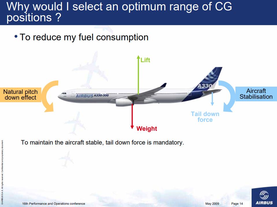
I did find a document supporting my case which seems to be official Airbus material:
Background information
I made an effort to make longitudinal static stability understandable below. Numbers, scale and distances are only for illustrative purposes and understand that this is a gross oversimplification of the actual subject but I hope its understandable.
Aerodynamic Center (AC)
When looking specifically at the wing, disregarding the horizontal stabilizer and other lift producing parts of the airframe:
The wing itself has a point, located at roughly 25% of the Mean Aerodynamic Chord (MAC) where the wing pitching moment (which is naturally nose-down) remains the same or is at least negligible with changes in angle of attack. To explain this effect, I have drawn two situations the green one represents straight and level flight, the red situation is following a disturbance increasing the angle of attack. Lets use the following numbers in this situation:
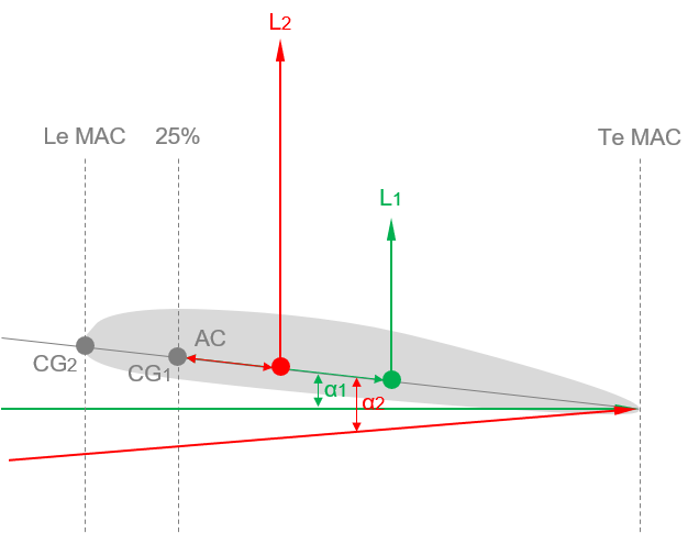
- Situation 1: lift force is 2 units, the moment arm from the CP to the AC is 5 units.
- Situation 2: lift force is 5 units, the moment arm from the CP to the AC is 2 units.
Moment = arm x force.
- Moment 1 = 2 x 5 = 10 units nose-down.
- Moment 2 = 5 x 2 = 10 units nose-down.
As can be seen, taking the AC as reference point the moment remains the same as the increase in magnitude is compensated for by a shorter moment arm. If we now take a reference point in front of the AC, for example the leading edge of the Mean Aerodynamic Chord (Le MAC) which is located 1 unit in front of the AC the moment change as follows:
- Moment 1 = 2 x 6 = 12 units nose- down.
- Moment 2 = 5 x 3 = 15 units nose-down.
Conclusion, the nose-down moment has increased, creating a restoring pitch-down moment. When taking a reference point behind the AC it will be vice versa, the nose-down moment will reduce with increase of angle of attack.
Neutral Point (NP)
If we now add the horizontal stabilizer to the equation we are going down a rabbit hole as we have to take into account the wing downwash effect on the horizontal stabilizer, its hard to know what this effect exactly is. All the sources I have dived into writing this suggest the angle of attack on the tail becomes more negative with an increase in angle of attack on the wing due to an increased downwash angle from the wing. Although I used this in my explanation below, I believe this to be more correct for smaller aircraft opposed to large airliners. So to elaborate a little further on this.
- If we completely disregard the effects of downwash from the wing on the horizontal tail (T-tail design), the angle of attack will increase on the horizontal stabilizer the same way as it does on the wing. The Neutral Point will be located behind the AC in this case as the reduced nose-down moment with increasing angle of attack will be compensated for by a reduced nose-up moment from the horizontal stabilizer.
- If we assume the wing downwash compensates for the otherwise increase of angle of attack on the horizontal stabilizer with increase of angle of attack on the wing (stabilizer angle of attack remains constant), the neutral point will be located on the aerodynamic center (we can basically remove the horizontal stabilizer from the equation),
- As in the situation below, if the downwash from the wing produces a more negative angle of attack on the horizontal stabilizer with an increase of angle of attack on the wing, the NP is located in front of the aerodynamic center.
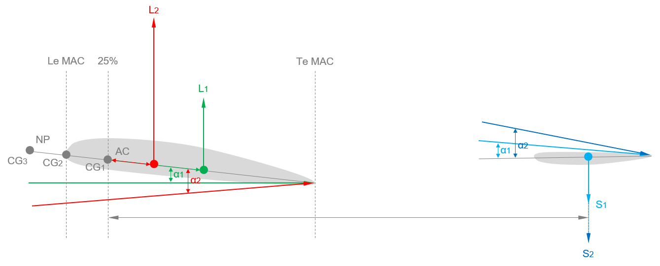
When including the effects of the horizontal stabilizer with the previous example, assuming the center of gravity is located on the AC and using an arm of 10 units and a down-force of 1 unit for the horizontal stabilzier in leve flight, increasing to 2 units following the disturbance:
-
Moment 1 wing = 10 units nose-down (previous example)
-
Moment 1 tail = 1 x 10 = 10 units nose-up
-
Moment 2 wing: 10 units nose-down (previous example)
-
Moment 2 tail: 2 x 10 = 20 units nose-up
As can be seen, following the disturbance the nose-down moment hasn’t changed while the nose-up moment has increased from 10 to 20 units. In conclusion the nose continues to rise and the aircraft is considered unstable.
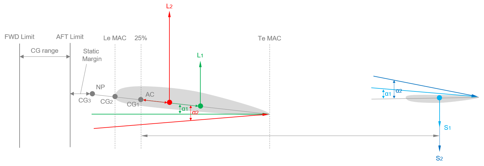
To reach neutral stability the CG must be located 2 units in front of the AC, be aware that if we change CG position the whole equation changes. Its not really that important in this example so lets continue using the same arm of 10 units for the horizontal stabilizer for simplicity. Following the disturbance:
Moment = force x arm
- Moment 2 wing = 5 x 4 = 20 units nose-down
- Moment 2 tail = 2 x 20 = 20 units nose-up
A point of neutral stability has now been reached, the aft CG limit is situated in front of this neutral point to attain static stability. Take the drawing below with a pinch of salt as the scale and location of points is fictional. The CG limits are located within the MAC normally. I haven’t found any information about the A320 or Boeing 747 but I know that for the Boeing 737 the Aft CG limit is very close to the aerodynamic center so I assume if you add everything together the neutral point will be located slightly behind the AC.
Hope it makes sense.